Communication issues develop for a number of reasons, including poor signal strength, low battery, damaged hardware, loose connections, or excess moisture inside connectors or enclosures. If loss of real-time data, intermittent performance, or signal failure occurs, the first troubleshooting step is to verify that the iSIC is powered.
1. Disconnect the iSIC from all external power sources (solar panel, battery, power supply, etc.). This can be accomplished by detaching the MS2 port connector, located on the bottom panel in the lower right corner of the enclosure.
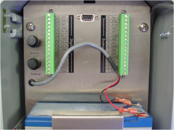
2. Open the iSIC, check the battery cable and wires for cuts or other damage.

Figure 1: Check iSIC for damage
3. Disconnect the leads and check the voltage across the battery using a voltmeter. It should be greater than 11.5 VDC.
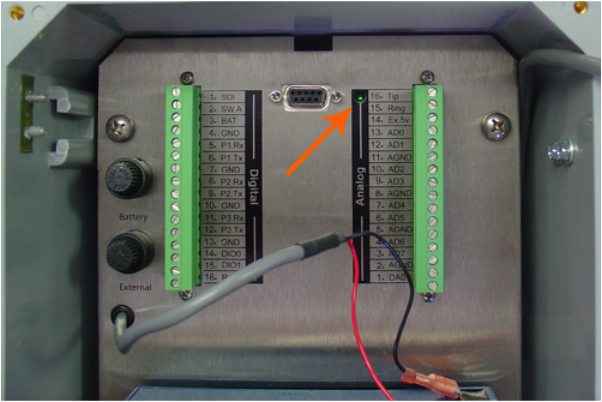
4. Reconnect the battery leads. Watch for the green LED above the analog strip to illuminate. It should blink slowly a few times, then quickly for a few seconds. Afterwards, it will turn off.

Figure 2: Verifying the iSIC start-up light pattern
5. If the LED does not illuminate, then the iSIC is not receiving sufficient power to operate or has an issue with the PCB. Contact NexSens for further troubleshooting.
REV: 13G16
