Use a multimeter to determine if there is a short or other issue affecting continuity within an RF Cable:
1. Set the meter to the resistance setting with the best resolution. On many meters, this will be the 200 ohm setting.
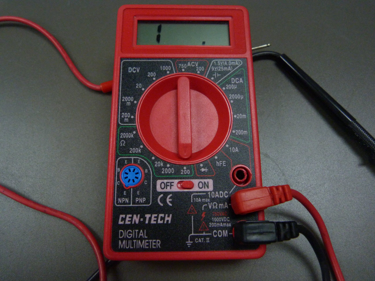
Figure 1: Multimeter Set To 200 Ohms
2. To determine if there is any internal resistance in the meter, cross the black and red probes and note the resistance shown onscreen. This number may be subtracted from future measurements.
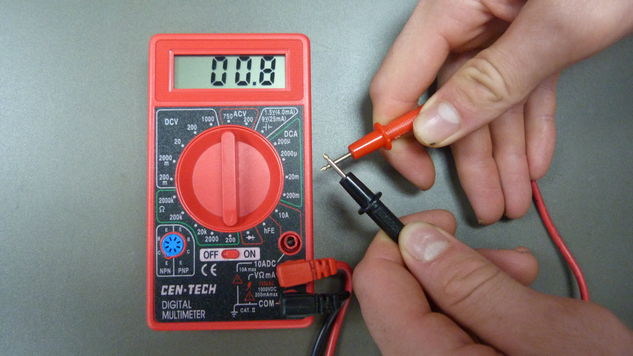
Figure 2: Check Internal Resistance
3. Gather the RF Cable. On each end of the cable, place one probe on the outside of its inner ring. The resistance should be close to 0 ohms.
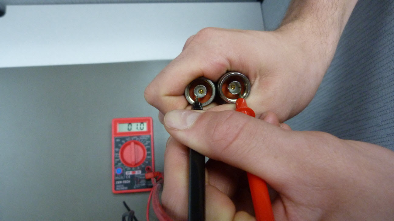
Figure 3: Confirm Outside Continuity
The meter in Figure 3 shows a resistance of 1.0 Ω, or about 0.2 Ω after subtracting 0.8 Ω.
4. Move the probes so that they are only touching the pins in the center of each ending connector. The resistance should be close to 0 Ω.
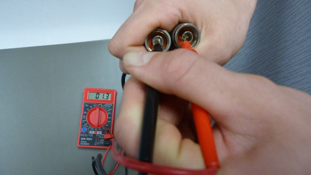
Figure 4: Confirm Inside Continuity
The meter in Figure 4 shows a resistance of 1.3 Ω, or about 0.5 Ω after subtracting 0.8 Ω.
If the resistance was found to be greater than about 5-10 Ω (depending on the length) during Step 4 or Step 5, the RF Cable should be replaced to avoid excessive signal loss.
5. Leave one probe touching a pin and move the other to the outside of the ring on the opposite ending connector. The meter should indicate an undefined/infinite resistance, meaning the lines are not shorted. Note that the value of “1” shown below indicates undefined or out-of-range resistance, not 1 Ω.
If a low resistance level (near-zero) is seen, the lines are shorted and the cable should be replaced.
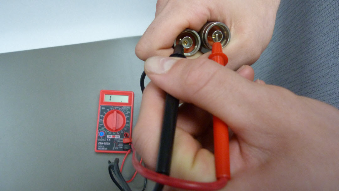
Figure 5: Check for Short in Cable
6. For longer cables, it may not be possible to measure resistance from both ends. To check continuity using only one end of the RF cable, place one probe on the center pin and the other on the outside ring:
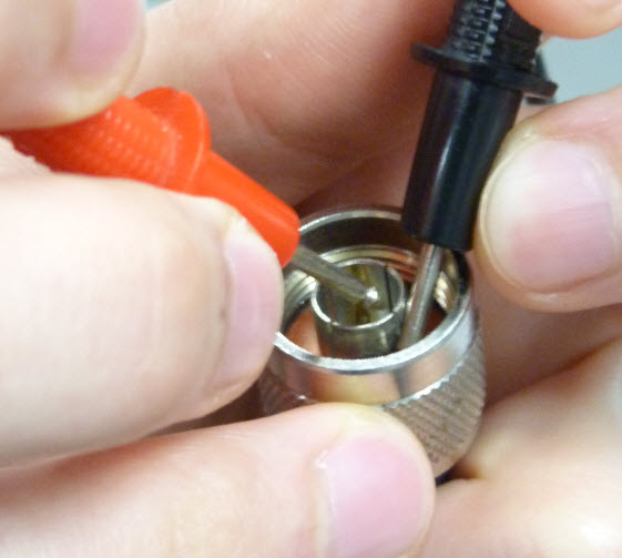
Figure 6: Check for Short in Long Cable
If there is no short in the cable, the meter should indicate infinite resistance. If a low level of resistance is shown (<200 Ω), there is a short in the cable and it should be replaced.
REV: 13J20

This is very helpful..thanks
Submersible Flat Cable Manufacturers