
The SDL is outfitted with various ports with different functionality. For the most part these are the same across all models, but the top port differs between a direct connect SDL500 and a telemetry version.
Pin Numbering
The ports on the SDL bulkheads are Underwater Receptacles (UW-R) that accommodate Underwater Plug (UW-P) connections from various sensors and communication devices. The mating plug’s signals are mirrored to those of the receptacle. For example, pin 1 on the receptacle mates with pin 8 on the plug.
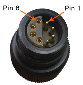
Figure 1: Pins on UW-Plug
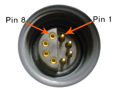
Figure 2: Pins on UW-Receptacle
Regardless of whether the UW connector is a plug or receptacle the pins are numbered in the same manner. With the pins on the right and the sockets on the left numbering is done clockwise starting with pin 1 at the 1 o’clock position and ending with pin 8 at the 11 o’clock position.
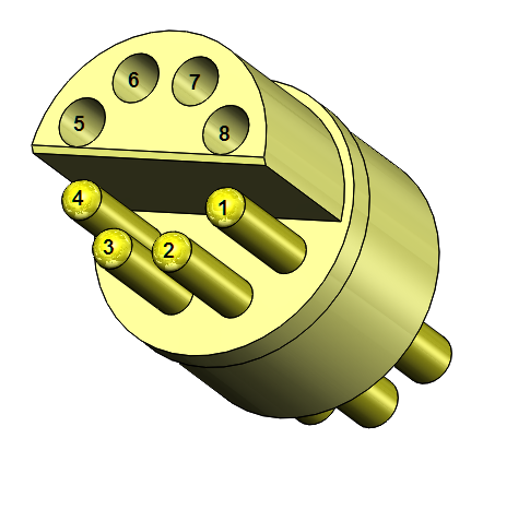
Figure 3: UW Pin Numbering
Shared Signaling
| Receptacle Pin | P0 | P1 | T | D | A |
|
1 |
485A | 485A | 485A | 485A | AD12 |
|
2 |
485B | 485B | 485B | 485B | AD13 |
|
3 |
SDI-12 | SDI-12 | SDI-12 | SDI-12 | AD14 |
|
4 |
BAT | SW12V | SW12V | BAT | SW12V |
|
5 |
SW5V | SW5V | SW5V | SW5V | DA1 |
|
6 |
P0.Rx | P1.Rx | 1-Wire | RAIN | AD15 |
|
7 |
GND | GND | GND | GND | GND |
|
8 |
P0.Tx | P1.Tx | P2.Rx | DIO0 | AGND |
Note that an underwater plug to flying lead cable can be used on sensor connection ports P0 and D (BAT and GND) to wire an SDL500 to external power devices. This is typically done on remote telemetry models, as they do not have access to external power connections via the top communication port without a splitter.
SDL500 Specific Signals
Direct SDL500 loggers are configured to provide host/sensor SDI-12, host RS-485, and host RS-232 signals on the top port.
| Receptacle Pin | Signal | Direction |
| 1 | H_RS485A | Input/Output |
| 2 | H_RS485B | Input/Output |
| 3 | SDI-12 | SDI-12 sensor or master. Firmware configurable. |
| 4 | BAT | Connect to external battery or supply power to external sensor. |
| 5 | H_RS232TX | Output |
| 6 | Power In | Input |
| 7 | GND | Signal and Power reference |
| 8 | H_RS232RX | Input |
Power can be supplied to the SDL through either pin 5 or pin 3 when no internal alkaline batteries are installed. With the presence of the SDL internal alkaline batteries, external power must be connected to pin 3 to avoid draining the internal batteries.
SDL500C/I/R Specific Signals
SDL500 loggers outfitted for telemetry (cellular, Iridium, or radio) have a top bulkhead port that is designed to allow the connection of an antenna. With this implementation the host RS-232 ports are lost as well as the ability to provide output power.
| Receptacle Pin | Signal | Direction |
| 1 | Host RS-485A | Input/Output |
| 2 | Host RS-485B | Input/Output |
| 3 | SDI-12 Data | SDI-12 sensor or master. Firmware configurable. |
| 4 | Key | N/A |
| 5 | Key | N/A |
| 6 | Power In | Input |
| 7 | Ground | Signal and Power reference |
| 8 | RF Center & Shield | Antenna Connection |
Flying Lead Cable
A UW to flying lead cable can be used to access the signals on all ports besides the top bulkhead port on a SDL500 with telemetry. Remember when using a flying lead cable, the pin numbers are mirrored.
| Receptacle Pin | Plug Pin | Wire Color |
| 1 | 8 | Green |
| 2 | 7 | Blue |
| 3 | 6 | Brown |
| 4 | 5 | Red |
| 5 | 4 | White |
| 6 | 3 | Yellow |
| 7 | 2 | Black |
| 8 | 1 | Orange |
Note: Observe caution when power is supplied to the data logger. All unused flying lead wires must be protected to prevent damage to nearby electronics.
REV: 16D18