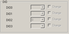
The iSIC data logger’s DIO0 and DIO1 lines are programmable digital input/output signals. In revision 6, the signals are 5V logic and can tolerate up to 6V. In revision 7, the signals are 3.3V logic and can tolerate up to 35V indefinitely. The most common use of these lines is to use them to drive a 3.3V or 5V logic relay. This process details how to check the status of these signals.
1. Open iChart without a current project.
2. From the main menu, select Advanced | iSIC | iSIC.
3. Select the correct PC COM Port, iSIC Address and the appropriate Connection. Click Connect.

Figure 1: Connecting to an iSIC
4. Switch to the General tab. If the “Status” group box is populated then a connection has been confirmed.
5. Click on the IO tab. It will take a few seconds to read and display the data.
6. The DIO lines that have been programmed and set as an output will have the “Change” check box enabled so that the signal state can be changed. To change the signal state, check “Change”, select either 0 or 1 and click Apply. This is used primarily as a troubleshooting technique.

Figure 2: DIO Signals
REV: 13G18
