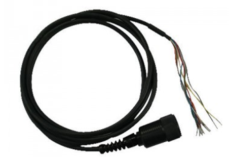
T-Node FR sensors can be connected to any iSIC data logger using a UW receptacle to flying lead cable assembly.

Figure 1: UW Receptacle to Flying Lead
First, plug the temperature string into the UW receptacle. Run the cable through a gland fitting on the bottom of the iSIC enclosure. Then, wire the flying lead end of the cable into the iSIC digital terminal strip per the wiring diagram below:
Wiring T-Node FR to iSIC Data Logger Digital Strip
| Wire | Signal | Pin |
| Brown | SDI-12 | 1. SDI |
| Red | 5-16V+ | 2. SW.A |
| Black | Ground | 4. GND |
| Yellow | Rx | 5. P1.Rx |
| Orange | Tx | 6. P1.Tx |
| Green | 485-A | 11. P3.Rx |
| Blue | 485-B | 12. P3.Tx |
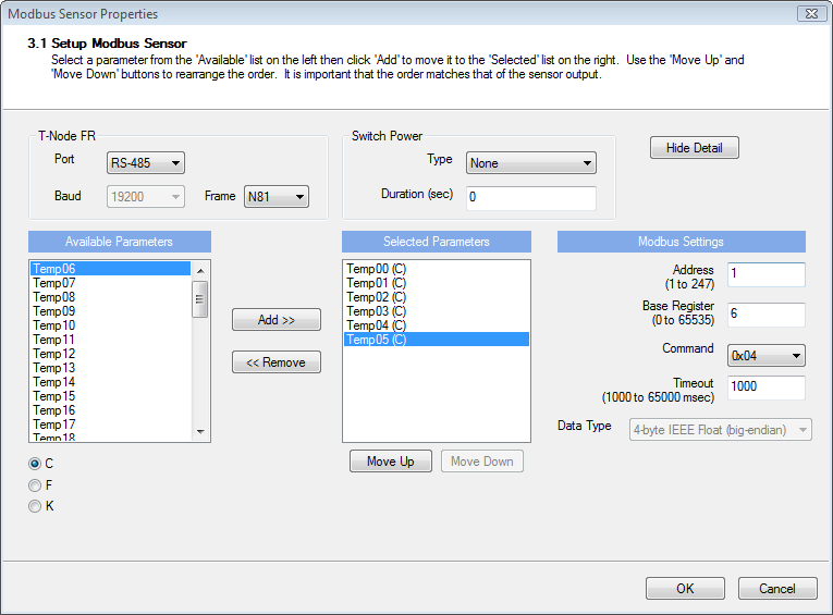
Note that the Red wire in pin 2 (SW.A) may be switched to pin 3 (BAT) on the digital terminal strip. If this is done, the T-Node FR string will have full power. A corresponding change should be made in the Sensor Properties window for the T-Node FR string. The Sensor Properties window can be accessed in the Setup Device Wizard or by right-clicking the T-Node FR string in iChart’s Navigation Panel (if the project file is setup) and then selecting Property. The Switch Power Type should be changed to “None” if the Red wire is switched to pin 3 (BAT).

Figure 2: If Red wire is switched from pin 2 (SW.A) to pin 3 (BAT), change Switch Power Type to “None” in the T-Node FR’s sensor properties window.
Connecting to an RS485 Modbus RTU Device
T-Node FR temperature sensors can also be connected to any device capable of reading RS485 Modbus RTU by utilizing a UW Receptacle to Flying Lead cable. To connect the temperature string to an RS485 Modbus RTU device, the following diagram may be used:
|
Receptacle Pin |
Wire Color |
T-Node FR |
|
1 |
Green |
RS485A |
|
2 |
Blue |
RS485B |
|
3 |
Brown |
SDI-12 Pass-through |
|
4 |
Red |
12VDC |
|
5 |
White |
5VDC Pass-through |
|
6 |
Yellow |
RS232 RX Pass-through |
|
7 |
Black |
GND |
|
8 |
Orange |
RS232 TX Pass-through |
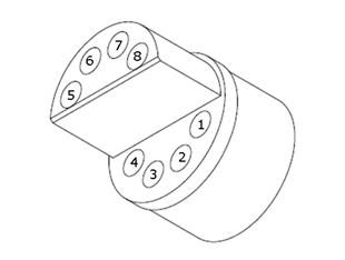
The pins are numbered as follows:

Figure 3: UW Receptacle pin numbering
REV: 13H06
