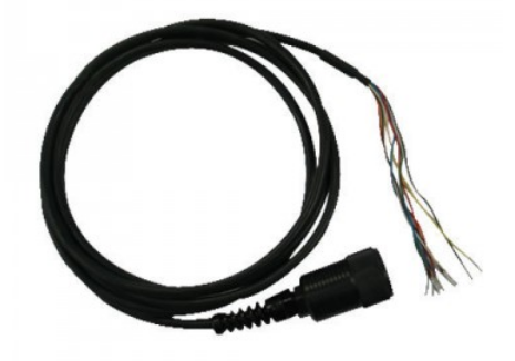
NexSens T-Node FR and TS210 temperature strings have an RS-485 Modbus output that allows direct connection to a Modbus master device (i.e. PLC). To connect the string, a UW receptacle to flying lead cable is required. These cables are available in lengths ranging from 1m to 100m.

Figure 1: UW Receptacle to Flying Lead Cable
The wiring for the T-Node FR or TS210 string to the Modbus master is shown in Table 1 below.
Table 1: T-Node FR/TS210 String to Modbus Master Wiring
| Wire Color | Signal |
| Red | 4-28VDC |
| Black | GND |
| Green | RS-485A |
| Blue | RS-485B |
* Wires not listed are not used and may be removed or tied off.
Register Information
Once connected, the following registers can be used to collect data and change the Modbus address of a node in the string.
Collect Data
| Function 0x04 (Read input registers) | |||
| Registers | Data Type | Data Size | Purpose |
| 0x0006 | 32-bit Float, Big-endian | 2 registers | Requests the temperature recorded by the node in Celsius |
Example, collecting data from Modbus Address 1:
| Collect Data | |||
| Request | Response | ||
| Field Name | Hex | Field Name | Hex |
| Slave Address | 0x01 | Slave Address | 0x01 |
| Function | 0x04 | Function | 0x04 |
| Start Address Hi | 0x00 | Byte count | 0x04 |
| Start Address Lo | 0x06 | Register Value Hi | 0x41 |
| Quantity of register | 0x00 | Register Value Lo | 0xAF |
| Quantity of register | 0x02 | Register Value Hi | 0x38 |
| CRC Lo | 0x91 | Register Value Lo | 0x1D |
| CRC Hi | 0xCA | CRC Lo | 0x0C |
| CRC Hi | 0x50 | ||
The response of 0x41 0xAF 0x38 0x1D converts to a Float value of 21.902.
Change Modbus Address
| Function 0x10 (Write multiple registers) | |||
| Register | Data Type | Data Size | Purpose |
| 0x1000 | 16-bit Integer | 1 register | Changes the Modbus Address of the node |
Example, changing address from 1 to 5:
| Change Modbus Address | |||
| Request | Response | ||
| Field Name | Hex | Field Name | Hex |
| Slave Address | 0x01 | Slave Address | 0x01 |
| Function | 0x10 | Function | 0x10 |
| Start Address Hi | 0x10 | Start Address Hi | 0x10 |
| Start Address Lo | 0x00 | Start Address Lo | 0x00 |
| Quantity of register | 0x00 | Quantity of Outputs Hi | 0x00 |
| Quantity of register | 0x01 | Quantity of Outputs Hi | 0x01 |
| Byte count | 0x02 | CRC Lo | 0x05 |
| Outputs Value Hi | 0x00 | CRC Hi | 0x09 |
| Outputs Value Lo | 0x05 | ||
| CRC Lo | 0x77 | ||
| CRC Hi | 0x92 | ||
0x05 is the new slave address of 5.
Read T-Node FR ID
| Function 0x04 (Write multiple registers) | |||
| Register | Data Type | Data Size | Purpose |
| 0x1007 | 32-bit Integer, Big-endian | 2 registers | Reads the T-Node FR ID |
Example, reading node with Modbus Address 1:
| Read T-Node FR ID | |||
| Request | Response | ||
| Field Name | Hex | Field Name | Hex |
| Slave Address | 0x01 | Slave Address | 0x01 |
| Function | 0x04 | Function | 0x04 |
| Start Address Hi | 0x10 | Byte count | 0x04 |
| Start Address Lo | 0x07 | Register Value Hi | 0x00 |
| Quantity of register | 0x00 | Register Value Lo | 0x10 |
| Quantity of register | 0x02 | Register Value Hi | 0x01 |
| CRC Lo | 0xC4 | Register Value Lo | 0x09 |
| CRC Hi | 0xCA | CRC Lo | 0x3B |
| CRC Hi | 0xD7 | ||
The four bytes 0x00100109 represent the ID for the T-Node FR.
If the addresses of all T-Node FRs in a string are known, the address of a single node may be changed while it is in the string using the Change Modbus Address command above.
For T-Node FR strings configured by NexSens, the first node is assigned Modbus address 1 unless otherwise noted. Each successive node has a value one higher than the previous node (2, 3, 4, etc.). TS210 strings are always configured in this manner unless requested otherwise.
IMPORTANT NOTE: Use extreme caution when changing the address of a node in a TS210 string to ensure that the nodes remain in numerical order and the same address is not assigned to more than one node simultaneously.
REV: 15B17
