When troubleshooting any data logger, confirming successful direct communication is an important early step.
Check LED
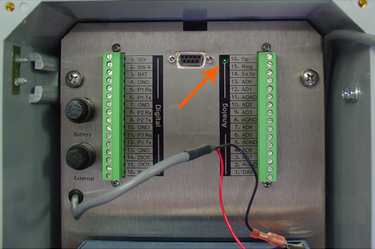
If an iSIC is being used, the LED status light can be observed during boot-up. This is not possible with a SDL or CB-iSIC as the LED is hidden internally.
- Cycle power to the iSIC
- As soon as power is re-applied, look in the small hole above the analog terminal for the green LED to blink
Check Terminal Output
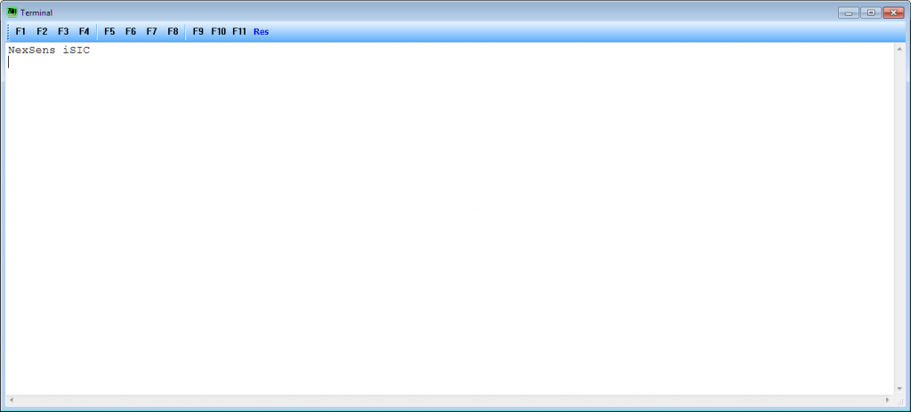
The most basic form of communication is the terminal output during data logger startup.
- Open iChart
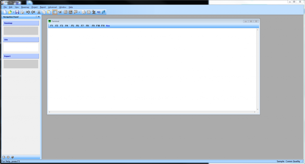
- Click on Advanced | Terminal
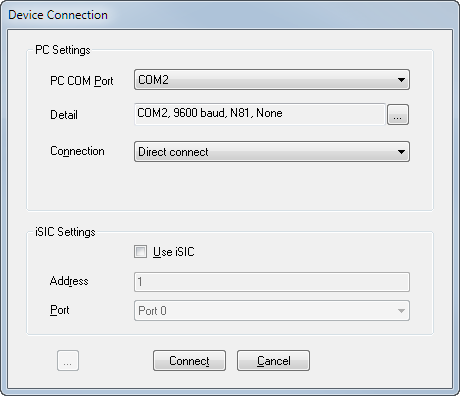
- Select the correct PC COM Port
- To determine the correct COM Port see the following article Verifying iSIC/SDL COM Port
- Confirm the Detail section shows 9600 baud, N81, None
- Choose the Connection type as Direct connect
- Click Connect

- Wait for a blank white screen to appear

- Connect the logger to the computer
- Cycle power to the logger
- See Cycling Power to an iSIC/SDL
- ***If using a UW-USB cable to connect to an SDL, this will power the logger and the UW plug needs to be removed from the SDL to fully cycle power.***
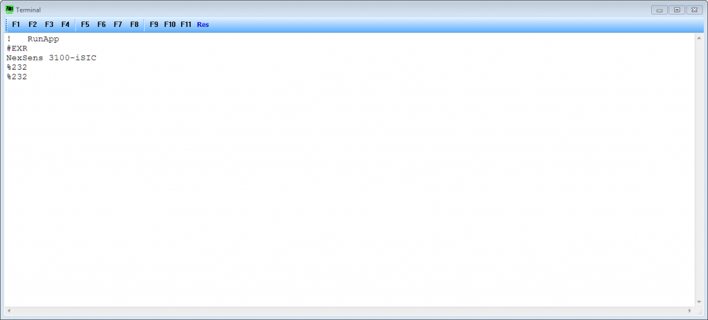
- If Connected via RS-232, the logger should output something similar to the following

- First line: ! RunApp
- Second line: #EXR
- Third line: NexSens <Device Type>
- Device type will show iSIC, 3100-iSIC, 4100-iSIC, SDL500, SDL500C, SDL500R, … depending on the type of logger connected
- Fourth line: <Permanent Communication Protocol>
- Permanent Communication Protocol will show %232, %TTL, %485 depending on the device’s configuration
- If %TTL or %485 appear, follow the following instructions to change the temporary protocol to %232
http://www.nexsens.com/knowledge-base/software/ichart/temporary-direct-connection-with-an-isic-data-logger.htm
- Fifth line: <Temporary Communication Protocol>
- Temporary Communication Protocol will show %232, %TTL, %485 depending on a user’s input
- This is what determines how the logger will interface with the computer
- Sixth line: <Other mode information>
- This line does not show up in most applications
- Other mode information includes things like SDI-12, Modbus, Iridium AT commands
- If Connected via RS-485, the logger should output something similar to the following

- First line: NexSens <Device Type>
- Device type will show iSIC, 3100-iSIC, 4100-iSIC, SDL500, SDL500C, SDL500R, … depending on the type of logger connected
- *Second line: <Permanent Communication Protocol>
- Permanent Communication Protocol will show %232, %TTL, %485 depending on the device’s configuration
- *Third line: <Temporary Communication Protocol>
- Temporary Communication Protocol will show %232, %TTL, %485 depending on a user’s input
- This is what determines how the logger will interface with the computer
- First line: NexSens <Device Type>
*These lines only appear if the user does an escape command
Check Advanced | iSIC | iSIC Communication
After confirming terminal output during power cycle, the next step is to confirm two-way communication.
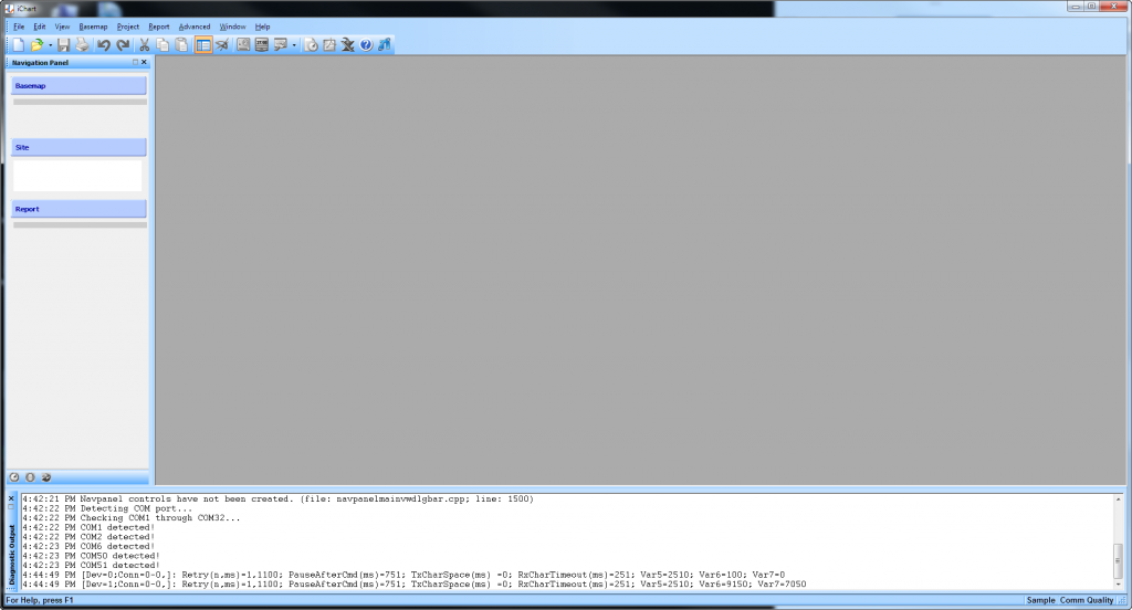
- In iChart click on View | Diagnostic Window to open the diagnostic window

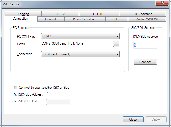
- Click on Advanced | iSIC | iSIC
- For PC COM Port, select the COM port that was used above when successfully seeing the terminal output
- Confirm the Detail section shows 9600 baud, N81, None
- For Connection, select iSIC (Direct connect)
- Leave the iSIC/SDL Address at 0
- Click Connect

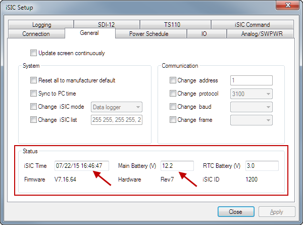
- After the button changes to Disconnect, click the General tab
- It should load up quickly if successful and look like the following
- Confirm battery voltage and date/time are read correctly

- If it does not load quickly, look at the diagnostic window for more information
- RETRY! and Fail sending CMD are an indicator that there is no communication between the computer and the logger
- Double check all connection settings
- Contact NexSens tech support for more assistance: Contact Us
- RETRY! and Fail sending CMD are an indicator that there is no communication between the computer and the logger
- Confirm battery voltage and date/time are read correctly
- If the date/time and battery voltage read correctly, direct communication has been confirmed
If communication failed at any point in this process, please confirm the correct COM port is being used, the cable is plugged in fully, the power supply/battery is good and if none of that works try adjusting the direct timing and re-trying the above steps.

