Install Software
To configure the 5500-iSIC WiFi module, install iChart and Device Installer software. To run iChart and access the 5500-iSIC, install the Com Port Redirector driver.
1. Insert the CD that came with the 5500-iSIC WiFi device. The installation screen should automatically be displayed. Click Software.
Note: The software may also be downloaded from the Downloads page on this website.
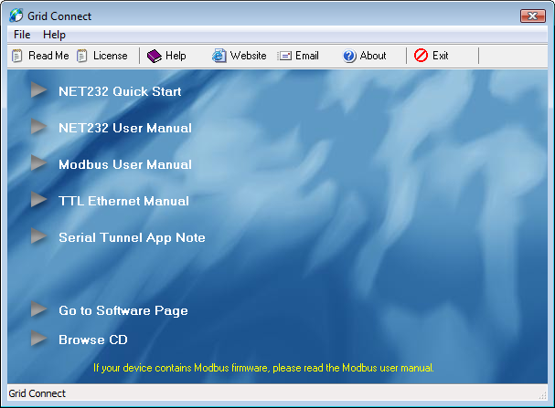
Figure 1: Grid Connect Software Installation Prompt
2. Next click on Go to Software Page.
3. Click .NET Framework Install and follow the installation wizard. This is required for the software to work correctly.
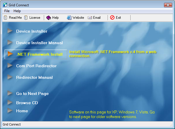
Figure 2: Install .NET Framework
4. After successfully installing the .NET Framework, click on Device Installer and follow the installation wizard. This will allow for setup of a specific IP address if needed.
5. After successfully installing the Device Installer, click Com Port Redirector (This will install CPR Manager and CPR Monitor) and follow the installation wizard. This will allow for accessing the 5500-iSIC through a virtual COM port.
Install iChart Software
Insert the iChart CD into your CD or DVD drive and follow the on-screen instructions to install iChart on the computer. If the installation does not start automatically, navigate to the iChart CD and double-click on the Setup.exe file to start the installation. If the iChart CD isn’t handy, the software can be downloaded from the NexSens website.
Configure the 5500-iSIC Wi-Fi Connection
First configure the 5500-iSIC Wi-Fi connection to be able to connect to the wireless router. At the minimum, set the 5500-iSIC SSID to your wireless router’s SSID. The 5500-iSIC supports both 802.11b and 802.11g standards. Both WEP (64 and 128 bit encryption) and WPA TKIP/AES are supported.
Next, connect one end of the RS-232 interface cable (A71) to the Wi-Fi module through the Null Modem adapter. Connect the other end of the interface to one of the computer COM ports.
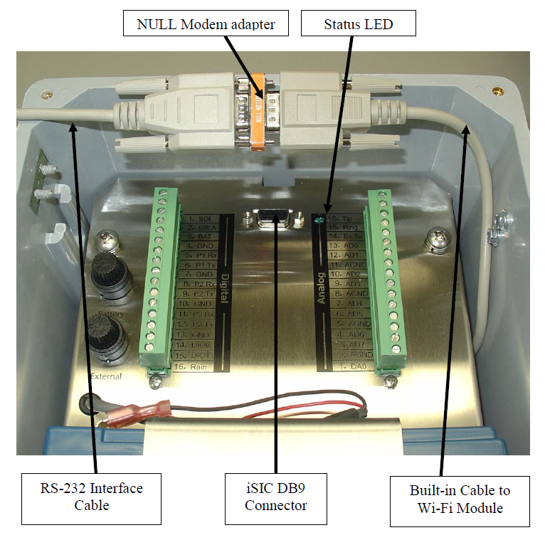
Figure 3: Connect one end of RS-232 Interface Cable to the computer and the other to the Wi-Fi module through the Null Modem adapter
From Windows Start menu, select All Programs | NexSens | iChart6 | iChart6 to run iChart. The program can also be opened by double-clicking its desktop icon.
When prompted, select the “Open Without Project” option.
When iChart opens, click Advanced | Terminal to open the Terminal. The Device Connection window will appear.
- Under “PC COM Port”, select the COM port on your PC that the RS-232 Interface Cable is connected to.
- Under the “Connection” drop-down list, select “Direct connect”
- Uncheck “Use iSIC”
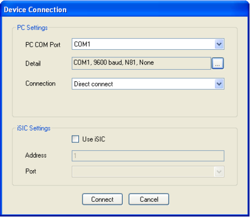
Figure 4: Device Connection window
Click Connect to open a terminal to the Wi-Fi module.
Apply power to the 5500-iSIC.
Watch the Status LED through the hole between the iSIC DB9 connector and the Analog terminal on the 5500-iSIC. When power is first applied, the LED blinks at a rate of once per second. After 5 seconds, the LED begins to blink in rapid succession.
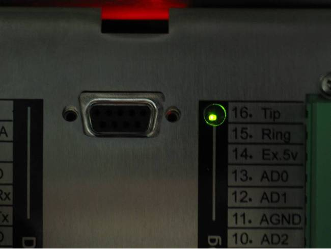
Figure 5: Green blinking LED
When it begins to blink rapidly, keep hitting the ‘x’ key on the keyboard until you see the Wi-Fi module boot message in the terminal. The MAC address on the terminal must match the MAC address found on the 5500-iSIC label. If a boot message isn’t seen after 10 seconds, turn off power to the 5500-iSIC and then apply power again, making sure the ‘x’ key is pressed at the right time.
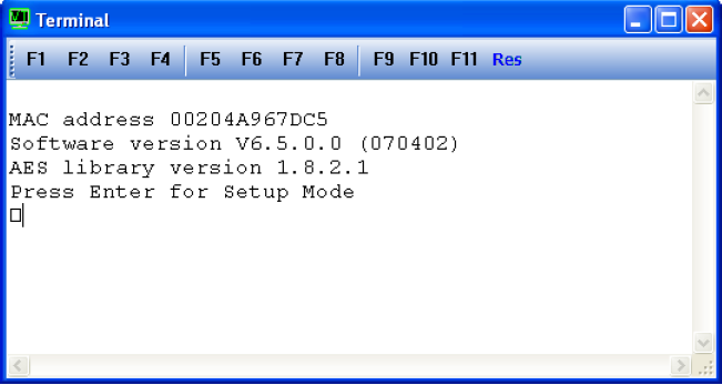
Figure 6: 5500-iSIC Terminal Message
Press the Enter key within 5 seconds after the boot message is displayed to enter the setup menu.
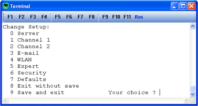
Figure 7: Setup menu for Wi-Fi module
Note that the question mark as shown indicates that it is too late to press the “Enter” key. Cycle power (turn off, then on) to the 5500-iSIC and repeat the steps above.
Select the number “0” to assign the IP address and network configuration. Obtain the following information from an IT administrator and manually enter as prompted:
- IP address assigned to this 5500-iSIC
- Subnet mask
- Default gateway IP address
Select option 4 to setup the wireless LAN. Obtain the wireless router SSID and security settings from an IT administrator and enter them as prompted. Be sure the network topology is set to Infrastructure.
- Topology: 0=Infrastructure, 1=Ad-Hoc (0) ?
- Network name (SSID) (LTRX_IBSS) ?
- Security suite: 0=none, 1=WEP, 2=WPA, 3=WPA2/802.11i (0) ?
Select option 9 to save changes and exit. Disconnect the RS-232 Interface Cable and the Null Modem adapter. Connect the Built-in Wi-Fi module cable to the 5500-iSIC DB9 connector. Cycle power on the 5500-iSIC (power off, wait 10 seconds, power on).
Confirm the 5500-iSIC Wi-Fi Connection
After the computer is rebooted, run Lantronix Device Installer to confirm the wireless connection. The Device Installer must run on a computer that resides on the same local area network that the 5500-iSIC is connected to.
From Windows Start menu, select All Programs | Lantronix | DeviceInstaller | Device Installer to run the Device Installer.
After started, the Device Installer automatically detects the 5500-iSIC on the network. If not, click the Search button to initiate the search. After the search is completed, the 5500-iSIC will be listed on the right panel of the Device Installer main window. Record the IP Address of the device with the Hardware Address that matches the 5500-iSIC MAC address.
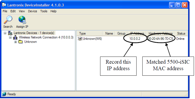
Figure 8: Lantronix Device Installer IP Address and MAC Address
Note: If the 5500-iSIC is set to a static IP address and then moved to a network with a different subnet, the only way to connect to it is through the device’s serial port. The Device Installer software will only detect 5500-iSIC data loggers configured with an IP address on the same subnet.
Configure COM Port Redirector
Com Port Redirector maps a virtual COM port on the PC to the 5500-iSIC so that the 5500-iSIC may be accessed as if it is connected directly to the computer COM port. From Windows Start menu, select All Programs | Lantronix | CPR 4.3 | CPR Manager to run the COM Port Redirector (CPR Manager) configurator.
From the CPR Manager dialog, select and record the redirect COM port number. This will be needed when running iChart later.
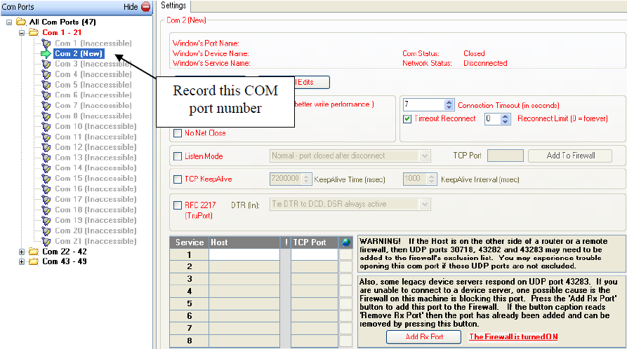
Figure 9: CPR Manager window
From the CPR Manager dialog:
- Enter the IP address recorded from the previous section for Host.
- Enter 10001 for TCP Port.
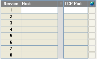
Figure 10: IP address in Host. TCP Port should be 10001
- Enter 7 for Connection Timeout.
- Enter 0 for Reconnect Limit.

Figure 11: Connection Timeout: 7 seconds, Reconnect Limit: 0
Press Save and exit the CPR Manager.
Test the 5500-iSIC Connection
Open iChart. When prompted, select Open Without Project. Select Advanced | iSIC | iSIC.
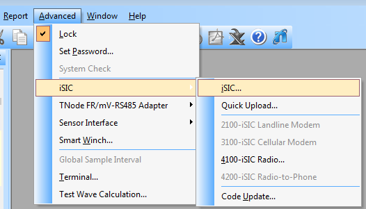
Figure 12: Advanced | iSIC | iSIC
On the PC COM Port drop-down list, select the COM port recorded from the previous section. Then click Connect. After iChart successfully opens the selected COM port, the button will change from Connect to Disconnect.
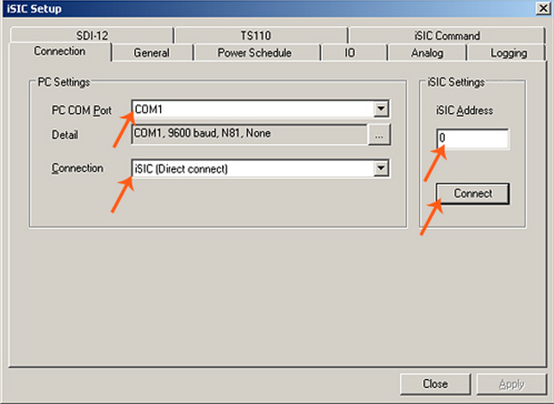
Figure 13: iSIC Setup window
Click the General tab. iChart will attempt to read the 5500-iSIC configuration. After it has finished reading the 5500-iSIC configuration, iChart will display it on the General tab. Verify that the iSIC Time is correct, the Main Battery is around 12V, and the Real-Time Clock (RTC) Battery is about 3V. Information on the firmware and hardware version of the board should also be displayed.
Click Close to return to iChart main window. iChart can be used to program the 5500-iSIC to collect data. Please refer to iChart and 5500-iSIC sections for more information.
Note this information and keep it for future reference:
- 5500-iSIC MAC Address
- SSID (case sensitive)
- 5500-iSIC IP Address
- 5500-iSIC IP Port (default 10001)
- 5500-iSIC Telnet Port (default 9999)
- Subnet mask
- Gateway IP
- Public IP Address
- Public IP Port
- Public Telnet Port
REV: 15E08
