Overview
The 3200-iSIC (Intelligent Sensor Interface and Control) features integrated spread spectrum radio and cellular modems for connecting via cellular telemetry to a radio network of 4100-iSIC data loggers.
What’s Included
- Data logger with spread spectrum radio and cellular modems
- 12 VDC battery
- A77 Programming cable
- iSIC Kit
- (2) Gland fittings
- (5) Desiccant packs
- RS-232 interface cable
- (4) 56 Ω resistors
Field Installation
1. Mount the data logger to a wall, pole, or other secure location above flood stage using the A55 Mounting Plate.
2. Connect the A38 grounding kit wire to the copper lug on the bottom of the 3100-iSIC data logger and the other end to an appropriate earth ground.
3. Mount the A49 cellular antenna in a location that will maximize signal strength. Attach an RF cable from the antenna to the cellular RF port on the 3200-iSIC.
4. Mount the A44 radio antenna in a location that will provide a line of sight to the radio data loggers in the network. Attach an RF cable from the antenna to the radio RF port on the
3200-iSIC.
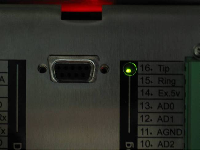
5. Power the iSIC by connecting the 12 volt battery. Observe the green blinking LED in the hole at the end of the analog terminal strip. This only blinks for 15-20 seconds during warm-up to confirm that the data logger is powered and ready.

Figure 1: Blinking Green LED Light
6. Typically the 3200-iSIC modem is factory activated and tested for cellular service. However, modems can be activated by the user. See the articles on activating cellular modems for more information: AT&T EDGE Modem, Sprint iDEN Modem, Verizon CDMA Modem.
Note: If a cellular account is not set up, the RS-232 iSIC interface cable can be used for direct connection.
7. Following modem activation, connect the cellular DB-9 cable inside of the enclosure to the DB-9 port between the green iSIC terminal strips.
8. Connect sensors to the data logger. See the appropriate sensor interface manuals for wiring and other details. Bring any cables into the enclosure by removing a port plug and
installing a gland fitting from the iSIC Kit.
Configuring with iChart
1. Install iChart software on a Windows computer.
2. Ensure power is supplied to the data logger.
3. Add the 3200-iSIC to an iChart project file. To accomplish this: Follow the Setup Device Wizard to add a site name, and then select 3200-iSIC from the list of NexSens data loggers. Enter the correct IP address at the prompt and click Test Connection to check communication.
4. Add sensors in iChart by selecting the manufacturer and model number.
5. Continue the Setup Device Wizard and click Program iSIC to conclude configuration.
REV: 13G18
