After repairs or diagnostics, it may be necessary to reinstall an iSIC data logger’s circuit board.
1. Mount the PCB to the mounting plate using (4) M3 x 16 screws and (4) M3 lock washers.
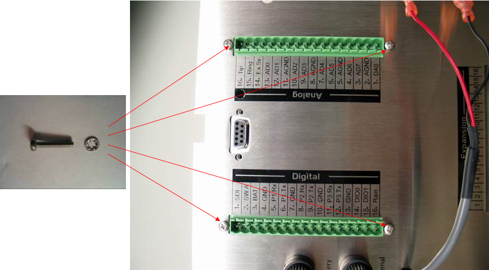
Figure 1: Mount PCB to iSIC data logger mounting plate using screws and washers
2. Turn the mounting plate over, place an M3 lockwasher and an M3 hex nut on the one screw in the corner shown.
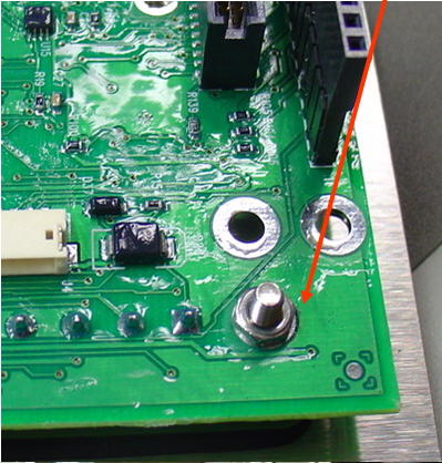
Figure 2: Attach hex nut to corner screw
Do not overtighten the screws.
3. Plug the MTA connector from the battery cable into the PCB (SLABAT position).
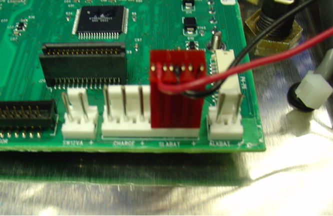
Figure 3: MTA Connector from battery cable in SLABAT position
Make sure the fastons from the battery cable are connected to the top fuse holder. The fastons must be completely latched onto the fuse holder plates.
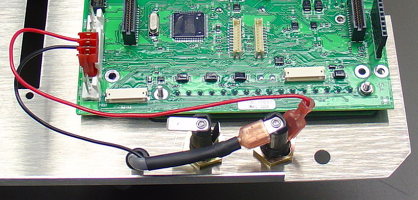
Figure 4: Fastons from battery cable connected properly
4. Plug the MTA connector from the MS2 Cable into the PCB (CHARGE position).
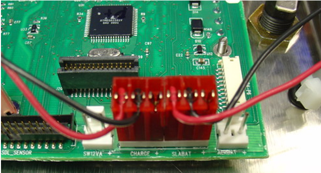
Figure 5: MTA Connectors
5. Connect the fastons from the MS2 cable to the bottom fuse holder.
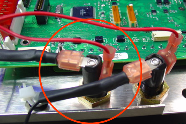
Figure 6: Connect fastons from MS2 to bottom fuse holder
6. Insert the JST connector from the MS8 cable into the socket on the PCB marked “MS8”.
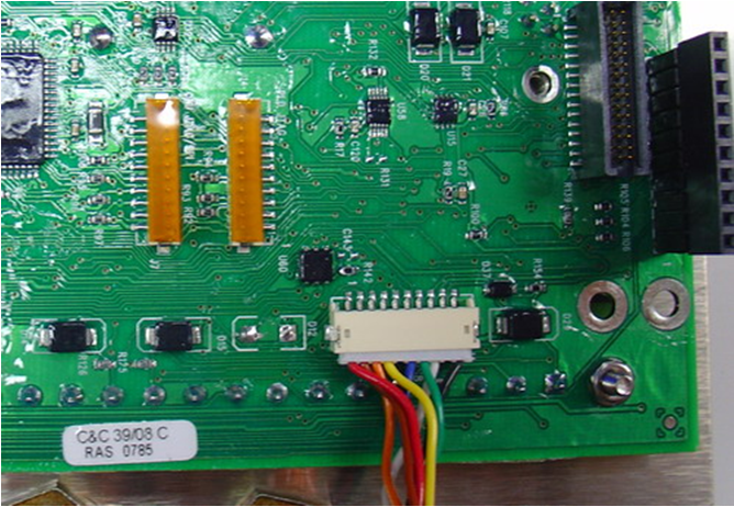
Figure 7: Connect MS8
7. Insert the JST connector from the MS3 cable, if there is one, into the socket on the PCB marked “P4-P6”. This connector is used for allowing direct connection from a PC serial cable to the MS3 port on some iSIC data logger enclosures. If cellular, radio or satellite telemetry is being used, this cable likely won’t be included. Data will be sent by the chosen telemetry method and the iSIC data logger will usually not have an MS3 port.
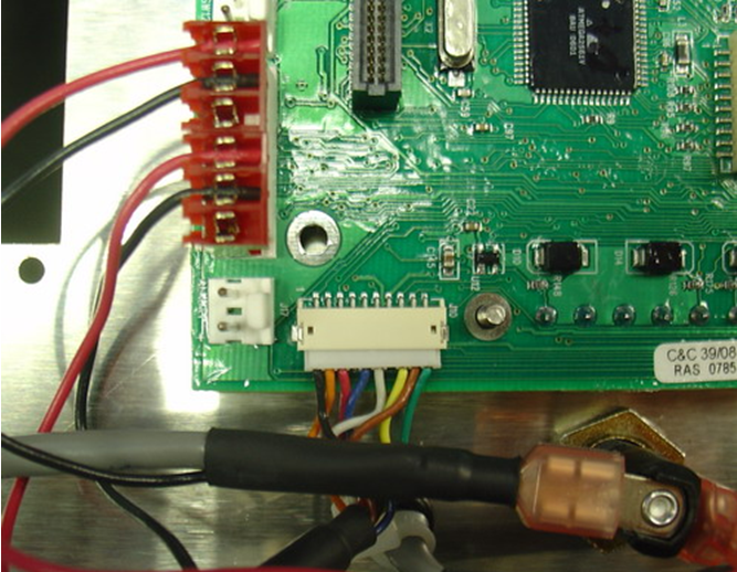
Figure 8: Insert JST connector from MS3 cable into socket marked P4-P6
If a cellular modem is attached to the board, make sure that its modem power cable is connected to the SW12VA pin. The RF cable should be connected to the RF connector on the modem and the modem serial cable should connect to the front of the iSIC data logger.
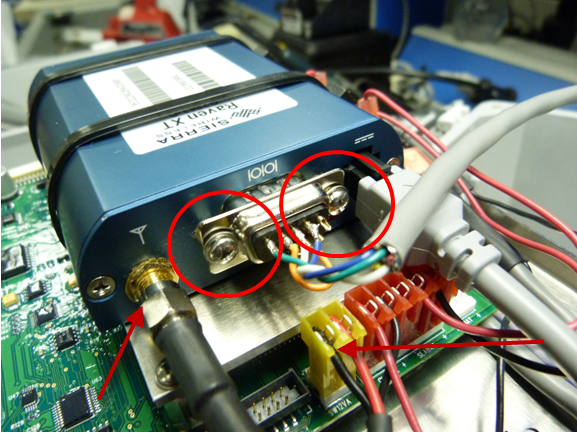
Figure 9: Sierra Wireless Raven XT Cellular modem connected to PCB. Far left arrow indicates RF Connection. Middle circles show serial cable connected to the modem – the other end of this cable connects to the front of the iSIC data logger. Far right arrow shows the modem power cable and its connection to SW12VA.
If a radio is attached to the board, make sure that the RF cable is connected to its RF connection. Note that the radio RF connection should be hand-tightened plus 1/4 turn.
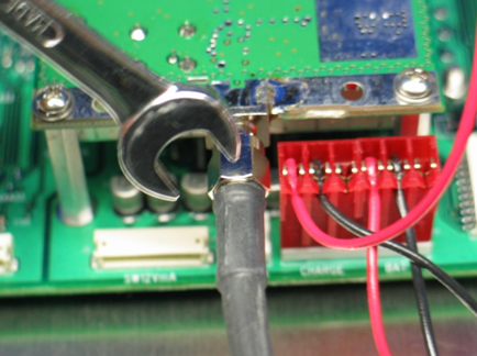
Figure 10: RF Connection on radio
8. Secure the mounting plate to the 2” standoffs using (4) ¼-20 x 3/8” screws and ¼-20 lock washers. Use a #3 Phillips head screwdriver.
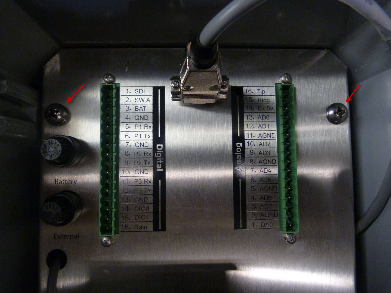
Figure 11: Secure mounting plate to standoffs using 4 sets of screws and lock washers. Note that this image shows a 3100-iSIC Cellular Data Logger, so the serial cable shown is connected to its cellular modem. This serial cable is not included on all iSIC data loggers.
9. Insert terminal strips.
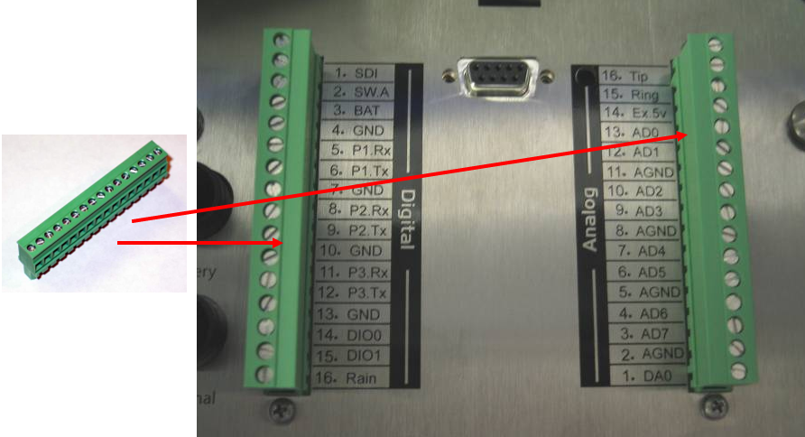
Figure 12: Connect terminal strips
10. Re-connect DB9 jack screws.
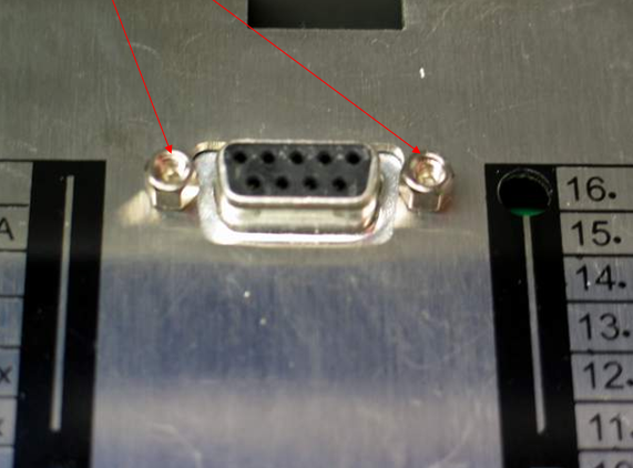
Figure 13: Put DB9 jack screws back in place
11. Re-wire as needed according to appropriate sensor interface guides
REV: 13H13
