Single-Ended (Non-Isolated) 4-20mA Sensors
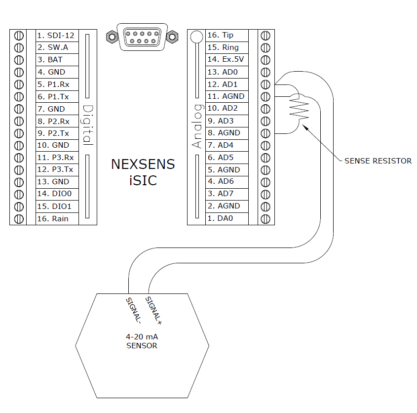
Connect single-ended 4-20 mA sensors to the internal analog terminal strip. A diagram of this is shown below:

Figure 1: Single-ended Non-Isolated 4-20 mA Sensor
Pins AD0 through AD7 can all be used for connecting 4-20 mA sensors. Eight 4-20 mA sensors can be connected at the same time using these pins on the analog terminal strip.
It is necessary for a sense resistor to be added into the wiring for each sensor to convert the current signal into a voltage signal. For convenience, four 56 ohm resistors are included with the iSIC. The included resistors have a 1% accuracy. It is recommended to check sensor documentation to find exact resistor requirements.
Differential (Isolated) 4-20 mA Sensors
Connect differential 4-20 mA sensors to the internal analog terminal strip. A diagram of this is shown below:

Figure 2: Differential (Isolated) 4-20 mA Sensors
Pins AD0 through AD7 can all be used for connecting 4-20 mA sensors. Eight 4-20 mA sensors can be connected at the same time using these pins on the analog terminal strip.
It is necessary for a sense resistor to be added into the wiring for each sensor to convert the current signal into a voltage signal. For convenience, four 56 ohm resistors are included with the iSIC. The included resistors have a 1% accuracy. It is recommended to check sensor documentation to find exact resistor requirements.
Loop Powered 4-20 mA Sensors
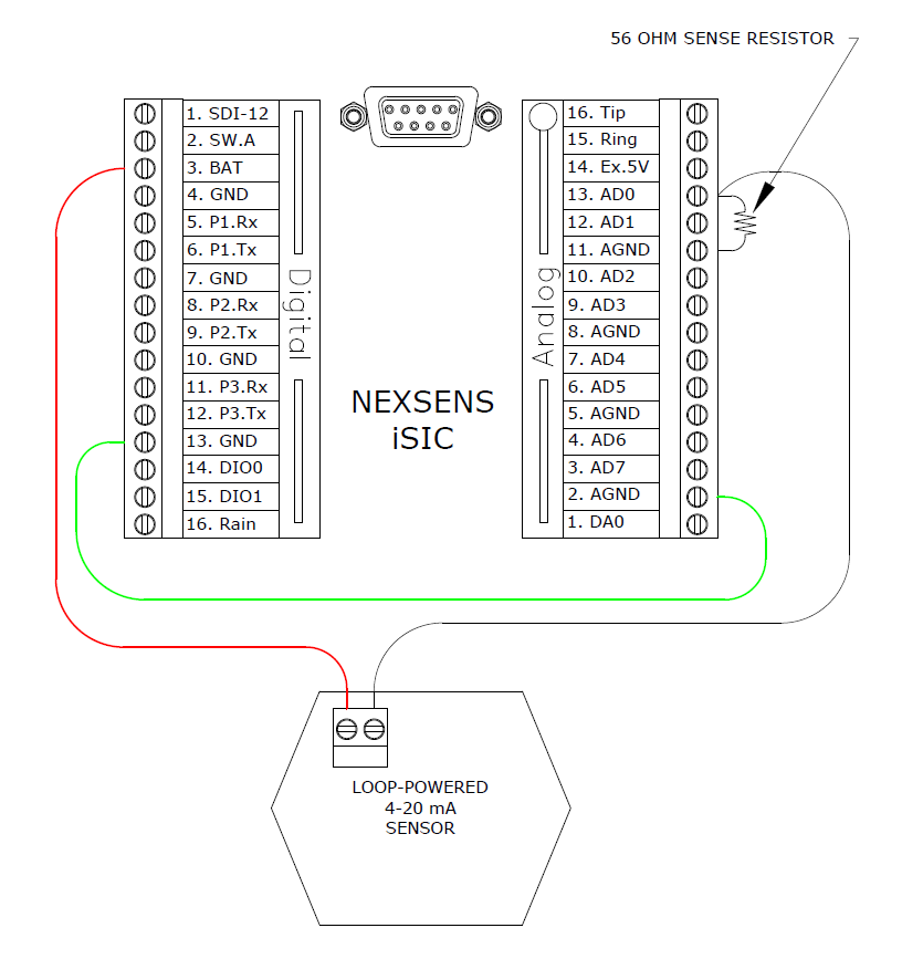
Connect loop powered 4-20 mA sensors to the internal digital analog terminal strip. A diagram of this is shown below:

Figure 3: Loop Powered 4-20 mA Sensors
Pins AD0 through AD7 can all be used for connecting 4-20 mA sensors. Eight 4-20 mA sensors can be connected at the same time using these pins on the analog terminal strip.
It is necessary for a sense resistor to be added into the wiring for each sensor to convert the current signal into a voltage signal. For convenience, four 56 ohm resistors are included with the iSIC. The included resistors have a 1% accuracy. It is recommended to check sensor documentation to find exact resistor requirements.
Note: GND and AGND are wired together because loop powered sensors require both digital and analog signals.
REV: 13G01
