Solar panel kits may be connected to iSIC data loggers to recharge the 12V A01 iSIC battery. Solar charging kits are equipped with a charge regulator to prevent overcharging of the A01 battery and damage to the data logger or connected devices. Use the following process to identify and troubleshoot suspected issues with a solar panel kit.
1. Check the solar regulator LED
- The solar regulator has an exterior LED status indicator. A flashing green LED indicates normal operation. A red LED indicates failure of the regulator. Replace the regulator immediately if a red LED is observed.
- By disconnecting the A01 battery inside the iSIC and covering the solar panel with an opaque material, the LED will stop flashing. When the battery is connected, the LED should flash green three times, and then flash periodically. Remove the opaque material to ensure that the normal flash pattern resumes.

Figure 1: Solar Regulator
2. Check the solar panel’s voltage
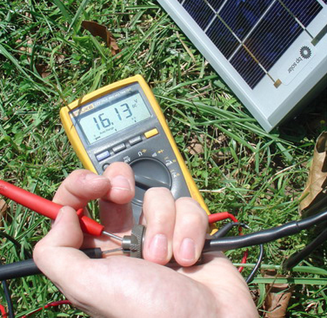
- Unplug the solar panel from the MS2 port on the bottom of the iSIC data logger. Using a voltmeter or multimeter set to measure DC voltage, apply the red lead to socket B and the black lead to socket A on the MS2 connector of the solar panel cable. The measured voltage should fluctuate rapidly from 0-18 V. Remove and replace the regulator if no voltage is measured or if the voltage is excessively high.
- Reconnect the MS2 connector when the test is complete.

Figure 2: Checking Voltage on Solar Panel MS2 Cable
3. Check voltages inside the regulator junction box.
- Using a voltmeter or multimeter:
1) Check the voltage across pin 2 (black) and pin 3 (yellow). The voltage should be around 18-22 VDC while in the sun.
2) Check the voltage across pin 2 (black) and pin 4 (red). The voltage should fluctuate between 6-20 VDC.
3. See the following links for instructions on removing and replacing a solar regulator:
Removing regulator: www.nexsens.com/knowledge-base/technical-notes/general/removing-a-solar-regulator.htm
Reinstalling regulator: www.nexsens.com/knowledge-base/technical-notes/general/reinstallling-a-solar-regulator.htm
REV: 14G31
