
Install a SIM Card into an X2 Data Logger
While it is always recommended that a SIM card be sent to NexSens for installation prior to shipment, in some cases it may be necessary for an end user to install a SIM card.
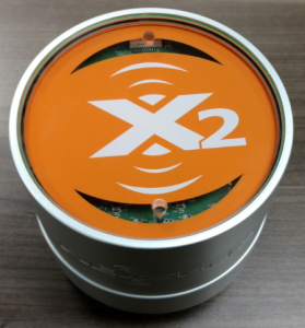
Figure 1: X2 Environmental Data Logger
Caution!!!- Be sure to statically ground yourself prior to touching any of the electronics inside the X2 logger!
Tools Required
- Small flathead screwdriver
- Phillips head screwdriver
- 3/16″ hex driver or adjustable wrench
Instructions
- Locate the green plastic wire from its track in the base of the X2’s aluminum housing.
- Slide tweezers or the tip of the screwdriver packaged with the X2 beneath the wire to expose it.
- Pull the end of the wire while applying pressure to the top of the X2 to remove it completely from the track. Tweezers or needle-nose pliers can be used if needed.
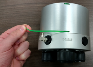
Figure 2: Pull the green wire out of the housing.
- Pull up on the enclosure to separate it from the X2 base.
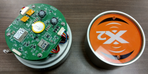
Figure 3: Separate the enclosure and the bulkhead.
- Press down on the tabs of the upward-facing UW-6 Direct and downward-facing UW-6 RTU JST connectors and gently pull to remove them from the main PCB.
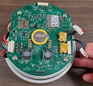
Figure 4: Remove UW-6 JST connectors.
- Remove the four visible Phillips-head screws and lock washers from the top of the main PCB.
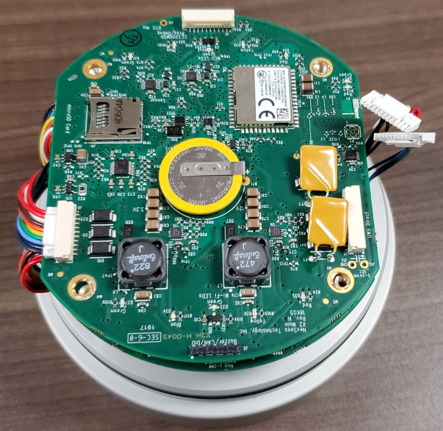
Figure 5: Remove the Phillips head screws.
- Gently lift up on the PCB to disconnect the board-to-board connector and expose the RTU PCB.
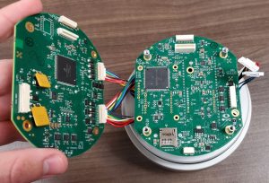
Figure 6: Separate the main and RTU boards.
- Use a 3/16″ nut driver or adjustable wrench to remove the four standoffs that hold the RTU PCB in place.
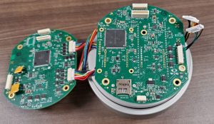
Figure 7: Remove the standoffs holding the RTU board.
- Carefully lift the RTU PCB to reveal the modem and SIM card slot.
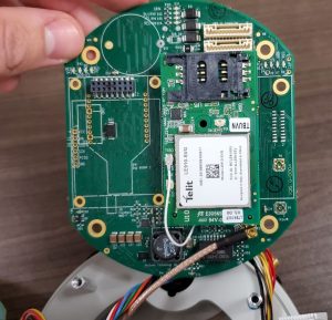
Figure 8: X2 cellular modem.
- Gently push the tray downwards to unlock it as indicated by the inscribed ‘open’ arrow on the tray.
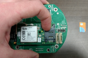
Figure 9: Unlock the SIM slot tray.
- Swing the tray lid open.
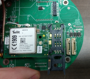
Figure 10: Open the tray lid.
- Place the SIM card in the tray such that the indentation on the card will align with the same indentation on the holder when closed.
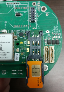
Figure 11: SIM inserted.
- Gently swing the tray closed and press upward gently to lock it back into place.
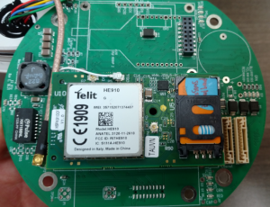
Figure 12: Close the tray.
- Place the RTU PCB back on top of the base and hand tighten the four standoffs back in place. Follow up with an additional 1/8 of a turn using the nut driver or adjustable wrench.
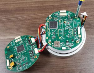
Figure 13: Reinsert the standoffs.
- Align the board-to-board connector and place the main board back on top of the RTU board, pressing down gently until the connector locks into place.
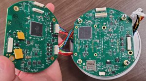
Figure 14: Reconnect the RTU and main boards.
- Tighten the top PCB back in place using the four Phillips screws and lock washers.
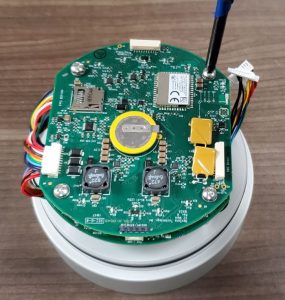
Figure 15: Reinsert the Phillips head screws.
- Reconnect the UW-6 RTU JST connector, gently pressing in until a click is heard.
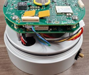
Figure 16: Reconnect the UW-6 RTU JST.
- Reconnect the UW-6 Direct JST connector.
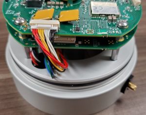
Figure 17: Reconnect the UW-6 Direct JST.
- Slide the enclosure back over top the X2 base, ensuring that no wires are pinched in the process.
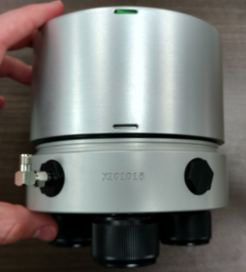
Figure 18: Push on the enclosure.
- Align the wire entry with the machined body tag on the aluminum base.
- Push down on the top of the enclosure and feed the wire back into its track.
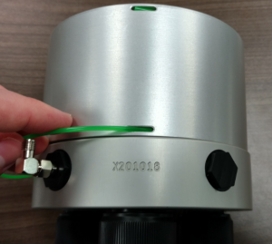
Figure 19: Reinsert the green wire.
- Connect the antenna and power up the X2, monitoring the blue LED blinking pattern above the X2 symbol at the top of the logger for up to 60 seconds to verify a successful cellular connection is established.
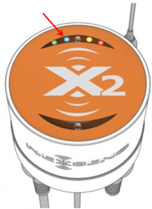
Figure 20: X2 LED indicators.
-
- A repeated pattern of three consecutive blinks indicates the X2’s attempt at cell connection was successful.
- A single repeated blink indicates the X2 is retrying the cellular connection.