Apply Power to the X2-SDL
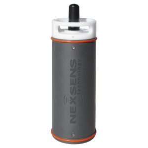
The X2-SDL has flexible power input choices that provide several options in terms of type and number of power sources.
Basic Requirements
- 5-24 VDC [+/-10%] (Reverse polarity protected)
- Current Draw (Typical @ 12VDC): Low power sleep: 350uA; Logger Active: 35mA; Wi-Fi Transmitting: 43mA; Cellular Transmitting: 300mA
- Peak Current: 500mA @ 12V for 1 second
Input Channels
The X2-SDL data logger is equipped with two separate power input channels. The logger pulls power from the highest priority channel that has a voltage within the specified range. If one of the sources falls outside the range, the next highest priority channel will automatically take over without an interruption in supply.
From highest to lowest priority, the channel order is as follows.
- Primary
- Backup
This multi-input design allows users to connect redundant power sources in order to mitigate the likelihood of system power loss.
Typical Application
Frequently, X2-SDL systems receive power from (16) internal D-Cell Alkaline batteries. The following article describes the process for installing these batteries properly before deployment.
Install Batteries In an X2-SDL Data Logger
Connector Wiring
Power may be applied to the X2-SDL via the UW-6 receptacle port by a UW-USB-485P for connection to a PC, or from a customized solar power kit. Most applications, however, rely on the internal D-Cell Alkaline batteries during deployment.
| X2-SDL UW6 Power Port Pinout | ||
| Pin Number | X2 Wire Color | Signal |
| 1 | Green | Host RS-485A |
| 2 | Blue | Host RS-485B |
| 3 | White | Backup Power Input |
| 4 | Black | Ground |
| 5 | — | — |
| 6 | Red | Primary Power Input |

Figure 2: UW-6 Pin Numbering.

