
Instrument Installation in CB-25 or CB-75 Data Buoy
The CB-25 and CB-750 Data Buoy have a solar tower plate allowing the installation of top-side mounts for GPS units and weather stations. Three 1.5″ sensor pass-through ports and the optional purchase of an EXO cage for the EXO series of YSI EXO sondes allow for multiple platforms for deploying subsurface water quality sensors.
Cage Installation
- Use a Philips head screwdriver to remove the top white plate from the solar tower.
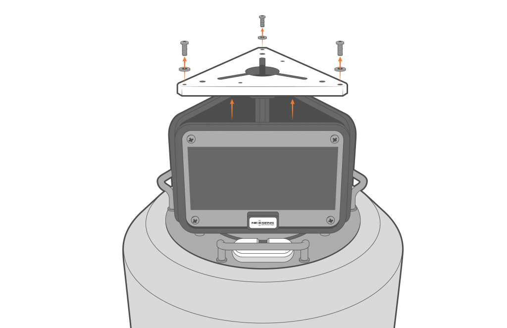
Top plate removal.
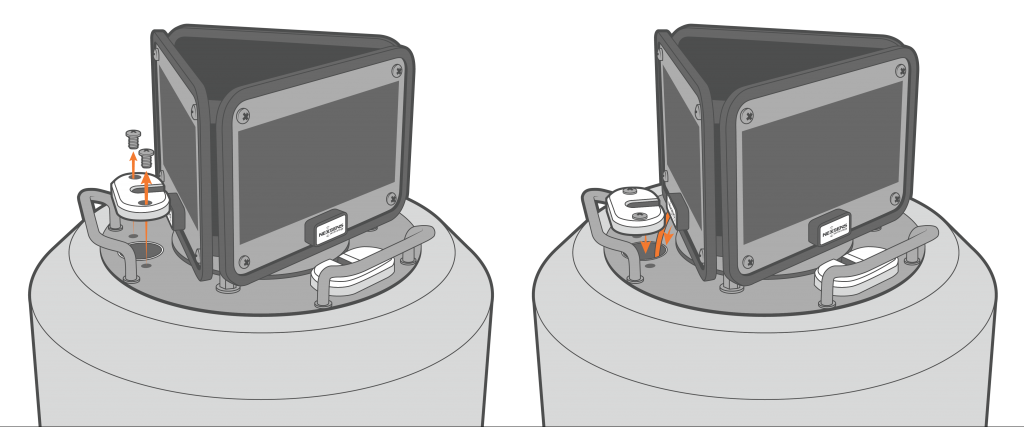
- Use a Philips head screwdriver to remove the internal screws on the solar tower.
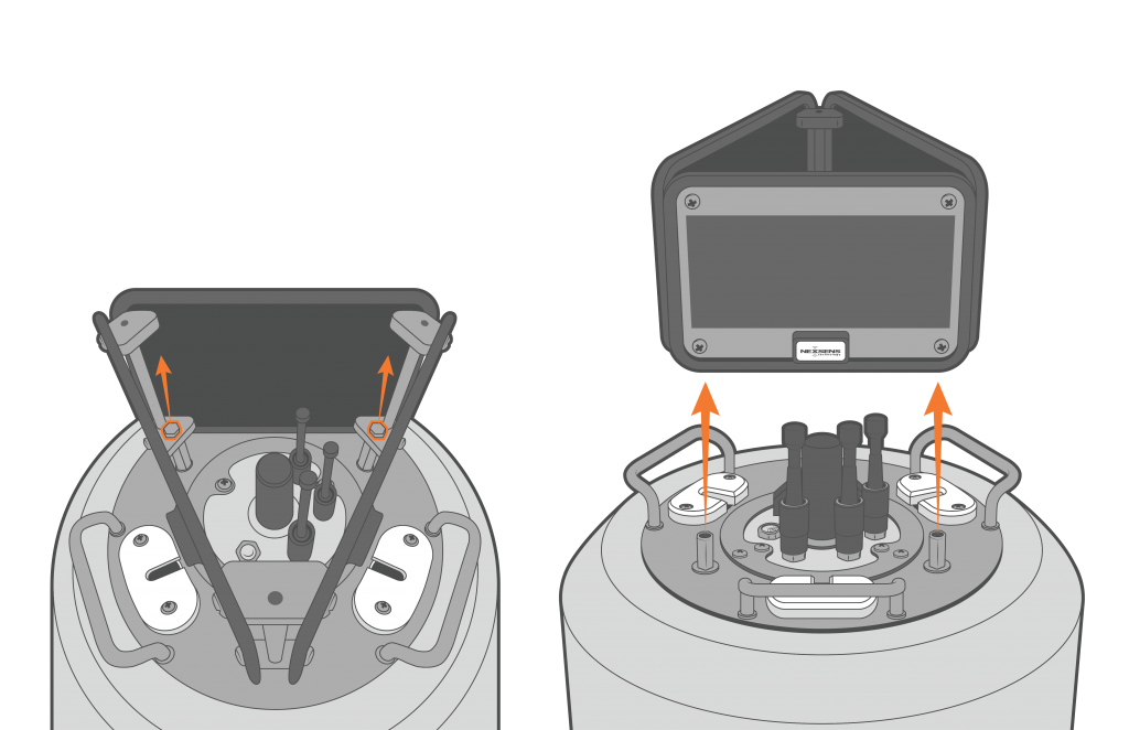
Solar tower removal.
- Use a Philips head screwdriver to remove the outside screws holding down the X2-SDLMC.
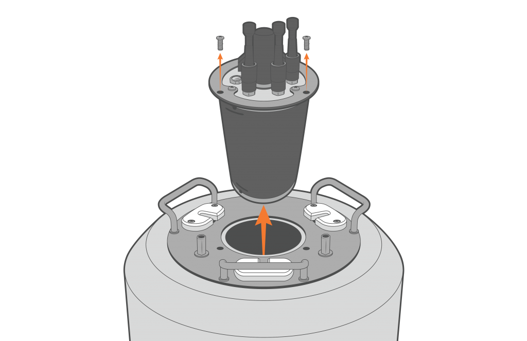
X2-SDLMC removal.
- Use the provided bolt, lock washer and castle nut to attach the cage to the buoy frame.
- Insert the bolt through the center hole within the buoy hull.
- Place the black ballast washer between the cage and the bottom buoy plate.
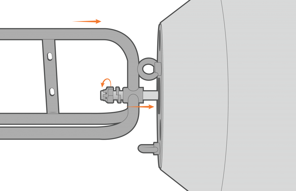
Bolt installation and cage connection.
- Tighten firmly with a pair of 1-1/8” wrenches.
- Ensure to flatten the lock washer and align the bolt hole with a notch on the castle nut.
- Place the cotter pin through the bolt hole and bend the long leg of the pin.
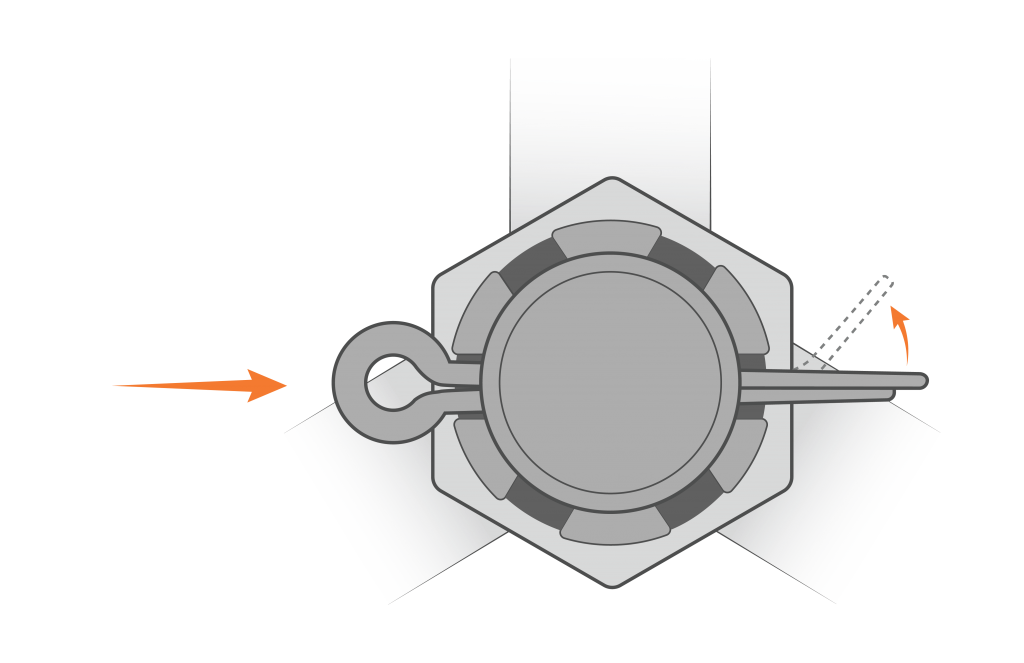
Cotter pin installation. Bent pin for security.
Sensor Cable Routing
- Route the sensor cables underneath the solar panel opposite the sensor ports.
- Ensure to insert enough cable within the solar tower to avoid tension on the connector.
- The connector should remain in a nearly vertical angle while connected.
- Use the included zip ties to secure the cable to one of the solar tower posts.
- Ensure to provide enough cable slack for
tension-free connections on both ends.
- Ensure to provide enough cable slack for
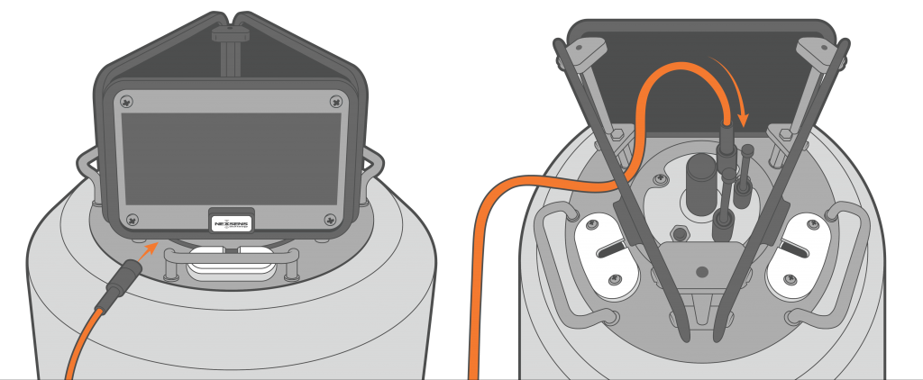
Sensor cable routing and connection.
- Remove the nearest sensor pass-through lid using a Philips screwdriver.
- Route the sensor cable through the passthrough tube.
- Align the sensor cable within the opening on the pass-through lid and re-install the lid.
Sensor cable routing through pass-through tube.