
mV-RS485 Adapter Pinout
User-wiring to a mV-RS485 adapter using a UW-FLx cable.
Only 0-2.5V sensor inputs are accepted. User must install voltage dividers if a chosen sensor has a higher native range.
Resistors must be wired in with 4-20mA sensors to convert signal to mV for adapter.
| Adapter Receptacle Pin | Signal | NexSens UW-FLx Plug Pin | NexSens UW-FLx Wire Color | NexSens UW-FWP Pin* |
| 1 | mV+ | 8 | Green | J8 |
| 2 | mV- | 7 | Blue | J7 |
| 3 | 100X Gain | 6 | Brown | J6 |
| 4 | V+ | 5 | Red | J5 |
| 5 | — | 4 | White | J4 |
| 6 | 10X Gain | 3 | Yellow | J3 |
| 7 | GND | 2 | Black | J2 |
| 8 | — | 1 | Orange | J1 |
*J-pin labels on the UW-FWP (i.e. 485B, 485A, SDI-12, etc.) do not match the signals on the mV-485 adapter besides GND and V+.

NexSens mV-RS485 Adapter receptacle pin numbering.
|
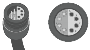
NexSens UW-FLx plug pin numbering.
|
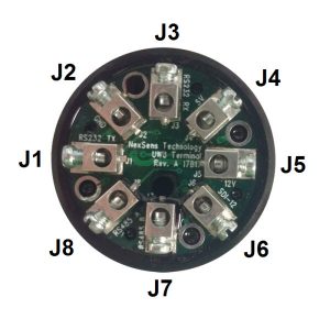
NexSens UW-FWP terminal pin numbering. |
|