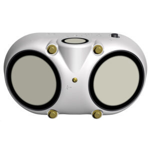
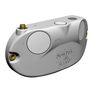
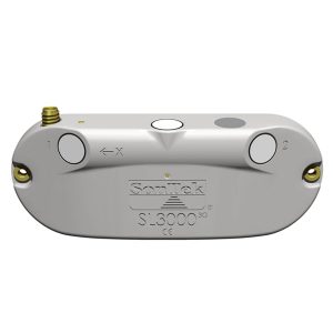
SonTek-SL Current Meter X-Series Integration Guide
Real-Time Water Velocity and Flow Measurements
The SonTek-SL Series of Side-Looking Doppler Current Meters measures water velocity and calculates overall flow in streams, rivers, and other water bodies. The sensors are compatible with the NexSens X-Series data loggers using the SDI-12 sensor interface and communication protocol. Parameter data is transmitted, in real-time, at a user-specified interval (e.g., 10 minutes) to the NexSens WQData LIVE Web Datacenter. There, data is stored on customizable dashboards with statistics and graphical interfaces for each parameter. Users can download and send data reports via Email, FTP, or an API. Below is information on the settings and wiring required to integrate SonTek SL-Series current meters with NexSens X-Series data loggers.
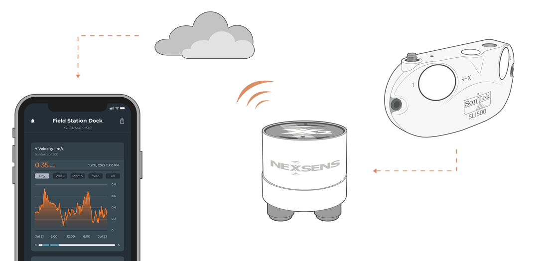
Figure 1: Integration of SonTek-SL Series of Side-Looking Doppler Current Meters with NexSens X-Series data loggers for real-time water velocity and flow measurements.
Compatible Models
SonTek provides three models of the SL-Series current meters – the SL500, SL1500, and SL3000. By updating the communication settings on either sensor, the sensors can output to the X-Series data logger, where a user-generated script logs the measurements. The script can gather data from 1 to 10 velocity cells and calculate the overall flow depending on the sensor’s channel configuration.
Current Meter Integration
All SonTek-SL Current Meters require an adjustment from the default SonTek Binary proprietary protocol to the SDI-12 protocol for communication with NexSens X-Series data loggers. The user must specify the SDI-12 address and the unit type (i.e., Metric or English units). A thorough review of the deployment site must be conducted. Specifically, the horizontal distance that the Sontek will need to measure water velocity and flow must be known. SonTek meters record water velocity at multiple horizontal distances, separated into cells, that are averaged into an overall integrated velocity. The user will need to know the overall horizontal distance to be measured so the number of cells and their sizes cover the required area.
1. Set the Deployment Settings
- Download and open the SonTek SL Software. Connect the SL power and communications cable included with the sensor. Click Connect for the software to detect the sensor and upload the current settings.
- Navigate to the Output Data section at the bottom of the interface and select Change.
- The Real time data (Units selection/Modbus/SDI-12/Analog) box should open.
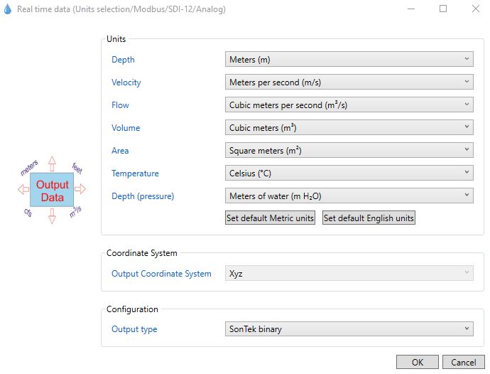
Figure 5: Sontek real time data output and units selection.
- Choose to use either Metric or English units.
- While individual unit selections are available, it is recommended to use either all Metric or English units for ease of creating the SDI-12 script.
- Ensure to note which units are utilized for future reference.
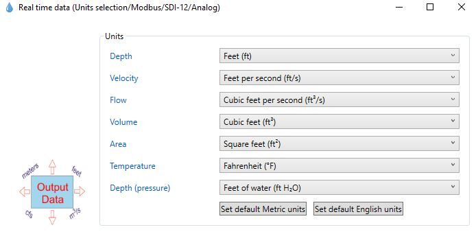
Figure 6: Default English units for SonTek meters. |
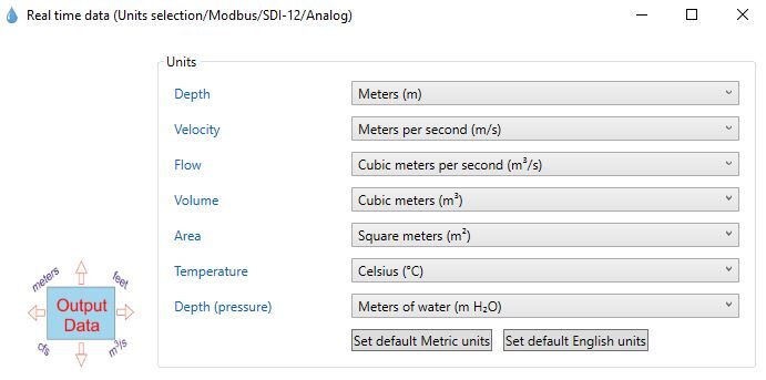
Figure 7: Default Metrics units for SonTek meters. |
- Change the Output Type from SonTek Binary to SDI-12 Output and select the proper SDI-12 address (0-9). Click OK when set.
- Ensure to note the SDI-12 address for future reference.
Set the Velocity Cell Number and Size
- Navigate to the Velocity Configuration section and select Change.
- Based on the required distance to measure the overall water velocity and flow, adjust the number of multi-cells (i.e., 1-10 cells) and their sizes (i.e., 0.16 to 2 meters).
- Ensure the Integrated Velocity Cell Begin and End are within the overall distances outlined by the velocity cells.
- Note the number of multi-cells selected, as the SDI-12 script will be determined by the overall cell count.
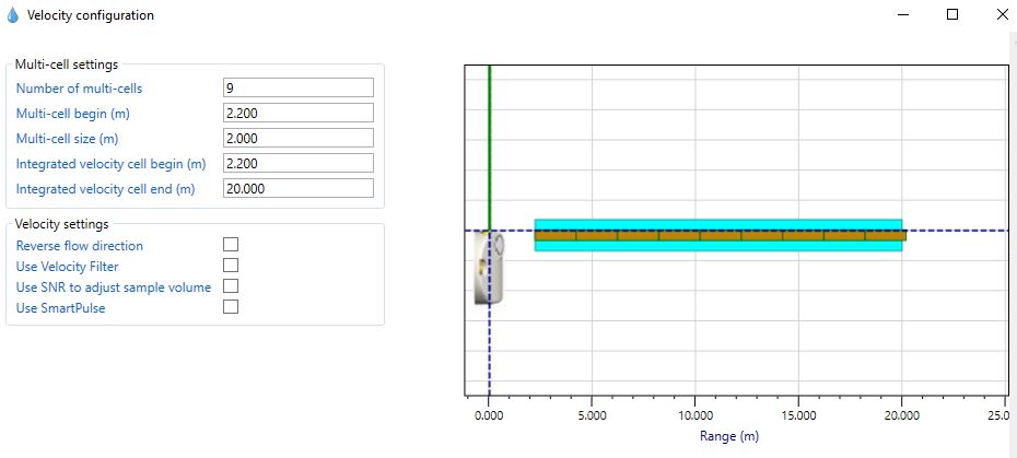
Figure 8: SonTek velocity configuration covering 9 total cells and an integrated distance of 20 meters.
Reference Section 3. Planning a Deployment – Smart Page of the SonTek user manual for more information on setting the velocity and flow configuration. Accurate channel dimensions are required to output flow values correctly. Flow is an available parameter; however, the flow configuration is not required for integration with NexSens X-Series data loggers.
2. Data Logger Connection
In nearly all applications involving NexSens integration, a NexSens waterproof UW8 plug will be added to the end of the sensor communication cable. Thus, the 10-meter cable can be connected directly to one of the ports on the NexSens X-Series data logger while the sensor is submerged at the appropriate location in the channel.
NexSens UW8 Connector Wiring & Pin Information
In the event of connecting a NexSens UW8 connector to an external device that is not an X-Series data logger, below is a link to the pinout of the NexSens UW8 connector, along with the pins associated with the communication, ground, and power signals.
SonTek Flying Lead
In the event of using the flying lead wires from the SonTek-SL current meters to wire into a NexSens A50 junction box, below is a wiring diagram for the connections between the SonTek cable and a NexSens plug to flying lead cable.
3. Automatic Sensor Detection
The user must create a Generic SDI-12 script through the NexSens CONNECT software to communicate and gather measurements from the SonTek Current Meter. The user must reference the SDI-12 address, number of multi-cells, and parameter units selected within the SL SonTek Software for proper configuration. Follow the link below to review the process for creating a Generic SDI-12 script through the CONNECT Software:
SDI-12 Script Generation
The SonTek manufacturer and model of the sensor can be pre-selected in the script generator. The measurement command should always be ‘C’, which allows for measurements to be obtained concurrently with other SDI-12 sensors connected to the logger. Switch power provides a balance between power consumption and data accuracy. SDI-12 sensors require a specific warmup time depending on the number of parameters to be measured. Determine the appropriate warmup time by communicating with the sensor in the CONNECT SDI-12 Tool:
- Communicate Directly with an SDI-12 Sensor
- By sending the ‘C’ command manually, the user can gather the number of seconds required to take a single reading. The SonTek-SL requires a 2-second overhead time to complete all calculations. The sample will be ready after a period no more than 2 seconds longer than the specified sample duration.
| Manufacturer | Model | SDI-12 Address | Port | Warmup | Measurement Command | Power |
| Sontek | SL (Metric or English) | 0-9 | P0, P1, or P2 | At least 2 seconds longer than the sample duration | C | Switch |
Sontek SDI-12 Parameter List
The SDI-12 ‘C’ command output varies slightly depending on the number of cells selected. For less than 10 cells, the last line will move to a lower register. Below are examples of the SDI-12 output of 5 and 10 cells. Parameters are in order from left to right, top to bottom (i.e., the first 5 parameters are Mean Temp, Mean Press, Stage, Multi-Cell End, and Integrated Velocity X).
5 Cell – SDI-12 Output
Note that cell 6 values will be reported as zeros to maintain the output structure. In the SDI-12 script, cell 6 values can be selected as “_None”, so the X-Series data logger will not log the measurements.
| Address | Command | Response | Output | |||||||
| 1 | 2 | 3 | 4 | 5 | 6 | 7 | 8 | |||
| 0-9 (0 used as an example) |
0C! | 0D0! | Mean Temp | Mean Press | Stage | Multi-Cell End | ||||
| 0D1! | Integrated Velocity X | Integrated Velocity Y | Overall Integrated Velocity | Integrated Velocity Mean SNR | Flow | |||||
| 0D2! | Vel.x (Cell 1) | Vel.y (Cell 1) | Vel.x (Cell 2) | Vel.y (Cell 2) | Amplitude (Cell 1 Beam 1) |
Amplitude (Cell 1 Beam 2) |
Amplitude (Cell 2 Beam 1) |
Amplitude (Cell 2 Beam 2) |
||
| 0D3! | Vel.x (Cell 3) | Vel.y (Cell 3) | Vel.x (Cell 4) | Vel.y (Cell 4) | Amplitude (Cell 3 Beam 1) |
Amplitude (Cell 3 Beam 2) |
Amplitude (Cell 4 Beam 1) |
Amplitude (Cell 4 Beam 2) |
||
| 0D4! | Vel.x (Cell 5) | Vel.y (Cell 5) | Vel.x (Cell 6) | Vel.y (Cell 6) | Amplitude (Cell 5 Beam 1) |
Amplitude (Cell 5 Beam 2) |
Ampltiude (Cell 6 Beam 1) |
Amplitude (Cell 6 Beam 2) |
||
| 0D5! | Battery (V) | Noise Beam 1 (SNR) |
Noise Beam 2 (SNR) | |||||||
10 Cell – SDI-12 Output
| Address | Command | Response | Output | |||||||
| 1 | 2 | 3 | 4 | 5 | 6 | 7 | 8 | |||
| 0-9 (0 used as an example) |
0C! | 0D0! | Mean Temp | Mean Press | Stage | Multi-Cell End | ||||
| 0D1! | Integrated Velocity X | Integrated Velocity Y | Overall Integrated Velocity | Integrated Velocity Mean SNR | Flow | |||||
| 0D2! | Vel.x (Cell 1) | Vel.y (Cell 1) | Vel.x (Cell 2) | Vel.y (Cell 2) | Amplitude (Cell 1 Beam 1) |
Amplitude (Cell 1 Beam 2) |
Amplitude (Cell 2 Beam 1) |
Amplitude (Cell 2 Beam 2) |
||
| 0D3! | Vel.x (Cell 3) | Vel.y (Cell 3) | Vel.x (Cell 4) | Vel.y (Cell 4) | Amplitude (Cell 3 Beam 1) |
Amplitude (Cell 3 Beam 2) |
Amplitude (Cell 4 Beam 1) |
Amplitude (Cell 4 Beam 2) |
||
| 0D4! | Vel.x (Cell 5) | Vel.y (Cell 5) | Vel.x (Cell 6) | Vel.y (Cell 6) | Amplitude (Cell 5 Beam 1) |
Amplitude (Cell 5 Beam 2) |
Ampltiude (Cell 6 Beam 1) |
Amplitude (Cell 6 Beam 2) |
||
| 0D5! | Vel.x (Cell 7) | Vel.y (Cell 7) | Vel.x (Cell 8) | Vel.y (Cell 8) | Amplitude (Cell 7 Beam 1) |
Amplitude (Cell 7 Beam 2) |
Ampltiude (Cell 8 Beam 1) |
Amplitude (Cell 8 Beam 2) |
||
| 0D6! | Vel.x (Cell 9) | Vel.y (Cell 9) | Vel.x (Cell 10) | Vel.y (Cell 10) | Amplitude (Cell 9 Beam 1) |
Amplitude (Cell 9 Beam 2) |
Ampltiude (Cell 10 Beam 1) |
Amplitude (Cell 10 Beam 2) |
||
| 0D7! | Battery (V) | Noise Beam 1 (SNR) |
Noise Beam 2 (SNR) | |||||||
Run the Sensor Detection
Once the script is created, transfer and enable it on the data logger.
After the script is enabled, run a sensor detection to program the sensor onto the logger.
Read Sensor Configuration – Confirm Sensor Detection
After ~5-10 minutes, read the sensor configuration to confirm the Sontek-SL and other sensors have been detected on the data logger. Thoroughly review the parameter list to ensure all parameters are accounted for and are measured in the desired units. Let the unit gather a few readings to confirm accurate and reasonable parameter data.
4. Setting up WQData LIVE
Once an X-Series data logger has finished a new sensor detection, it will automatically push the sensor configuration to the WQData LIVE web data center. Follow the three articles below to create a WQData LIVE account and a project/site. Then add the data logger to the project using the included claim code.
- Create a WQData LIVE Account
- Create a Project on WQData LIVE
- Add a Data Logger to a Project on WQData LIVE
Real-Time System Application
Real-time water velocity and flow measurements from the SonTek SL-Series of side-looking Doppler Current Meters are useful in various environmental monitoring applications.
Applicable Systems
Discover applicable uses for the SonTek SL-Series of Current Meters.

