Sea-Bird Scientific HydroCAT CTD X-Series Integration Guide
Real-Time Water Quality Measurements
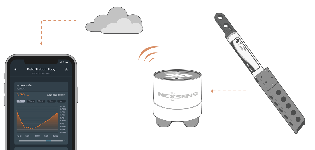
The Sea-Bird Scientific HydroCAT CTD is ideally suited for extended deployments in remote, biologically rich environments to measure conductivity, temperature, pressure, and optical dissolved oxygen. The sensor is compatible with NexSens X-Series data loggers using the SDI-12 communication protocol and sensor interface. Parameter data is transmitted, in real-time, at a user-specified interval (e.g., 10 minutes) to the NexSens WQData LIVE Web Datacenter. There, data is stored on customizable dashboards with statistics and graphical interfaces for each parameter. Users can download and send data reports via Email, FTP, or an API. Below is information on the settings and wiring required to integrate SonTek SL-Series current meters with NexSens X-Series data loggers.
Compatible Models
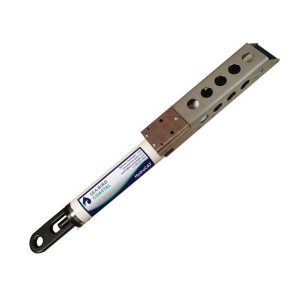
Sea-Bird produces multiple models of the HydroCAT CTD that differs in the available sensor suite. Optional dissolved oxygen and depth sensors are available. The available probes on the sensor will determine the parameter list that will output via SDI-12.
Sensor Integration
Using SDI-12 communication, the sensor will output a user-defined parameter list after receiving an SDI-12 measurement command from the logger. The internal script sends this command before each reading and allows enough warm-up time for the sensor pump. The user must define the available parameter list and create an SDI-12 script using the CONNECT software.
1. Wiring
Follow the wiring diagram below to connect your Sea-Bird Scientific HydroCAT CTD sensor to a PC by utilizing the Sea-Bird manufacturer-included MCIL-6-FS to DB9 software cable. An RS232-to-USB converter will be necessary to connect to a PC.
Warning: Ensure the red wire (voltage in) is only wired for the sensor and has no wiring connection with the RS-232-to-USB converter.
| MCIL-6-FS Pin # | DB9 Serial Pin # | External Wire Color | Signal |
| 1 | 5 | Black + Spare (Both black external wires) | GND |
| 2 | 3 | — | RS232 Rx |
| 3 | 2 | — | RS232 Tx |
| 4 | — | Yellow | SDI-12 |
| 5 | — | — | Reserved |
| 6 | — | Red | Voltage In |
2. Establish Software Connection
- Download and open the Sea-Bird Scientific UCI software for MAC or Windows.
- Under the UCI Dashboard tab, click Connect. A separate Connect window will open. Enter the following settings:
- Instrument Type: HydroCAT
- Baud Rate: 9600
- Choose the COM port connected to the sensor
- Click Connect when the settings are input.
- Once connected, the Connection Mode at the top left will display Setup in green, along with the internal sensor diagnostics.
3. Configure SDI-12 Output and Parameters
- Open the HydroCAT deployment wizard by going to Sensor | HydroCAT (no optics) | Deployment Wizard.
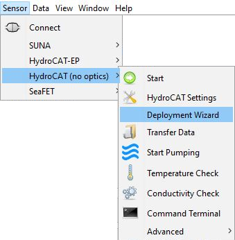
Figure 5: HydroCAT Deployment Wizard
- Set the operating mode to Polled Sampling (SDI-12).
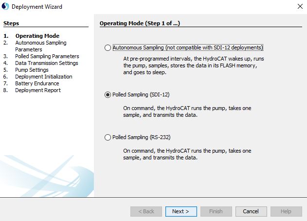
Figure 6: Deployment Wizard – Operating Mode
- Set the SDI-12 address value between 0-9. Ensure to note the SDI-12 address for future reference.
- It is recommended to keep the Bad Data Flag as default.
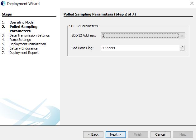
Figure 7: Deployment Wizard – Polled Sampling Parameters
- Modify the sensor output format based on the available parameters. Ensure to note the parameter order and units for future reference.
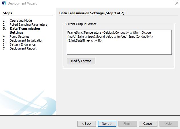 Figure 8: Deployment Wizard – Data Transmission Settings | 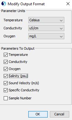 Figure 9: Deployment Wizard – Parameter Output Format |
- Adjust the pump settings based on the manufacturer-supplied calibration page and the salinity at the final deployment location.
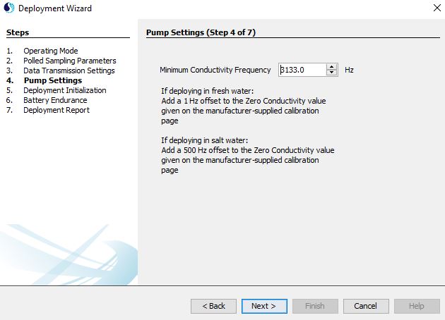
Figure 10: Deployment Wizard – Pump Settings
- It is recommended to sync the sensor clock with the local PC time and leave the polling as default in the Deployment Initialization and Battery Endurance sections, respectively.
- Save the Deployment Report for future reference and select Finish.
4. Automatic Sensor Detection
The user must create a Generic SDI-12 script through the NexSens CONNECT software to communicate and gather measurements from the HydroCAT CTD. The user must reference the SDI-12 address, parameter order, and parameter units selected within the UCI Software for proper configuration. Follow the link below to review the process for creating a Generic SDI-12 script through the CONNECT Software:
- Create a Generic SDI-12 Script in CONNECT
- The Sea-Bird manufacturer and HydroCAT SDI12 model are available for ease of use.
Run the Sensor Detection
Once the script is created, transfer and enable it on the data logger.
After the script is enabled, run a sensor detection to program the sensor onto the logger.
Read Sensor Configuration – Confirm Sensor Detection
After ~5-10 minutes, read the sensor configuration to confirm the HydroCAT CTD and other sensors have been detected on the data logger. Thoroughly review the parameter list to ensure all parameters are accounted for and are measured in the desired units. Let the unit gather a few readings to confirm accurate and reasonable parameter data.
5. Setting up WQData LIVE
Once an X-Series data logger has finished a new sensor detection, it will automatically push the sensor configuration to the WQData LIVE web data center. Follow the three articles below to create a WQData LIVE account and a project/site. Then add the data logger to the project using the included claim code.
- Create a WQData LIVE Account
- Create a Project on WQData LIVE
- Add a Data Logger to a Project on WQData LIVE
Real-Time System Application
Real-time water quality measurements from the Sea-Bird HydroCAT CTD are useful in various environmental monitoring applications.
Applicable Systems
Discover applicable uses for the Sea-Bird HydroCAT CTD.
Water Quality Measurements
Learn more about water quality measurements on the NexSens Blog Page.
Sensor Manual
For additional information on the Sea-Bird HydroCAT CTD, please refer to the Sea-Bird Scientific HydroCAT CTD Manual.

