Lufft WSxxx-Series Weather Stations X-Series Integration Guide
Real-Time Weather Measurements
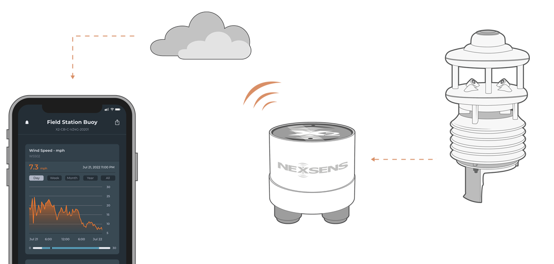
The Lufft WSxxx-Series of Weather Stations are compatible with NexSens X-Series data loggers via the Modbus-RTU protocol and the RS-485 sensor interface. A pre-defined script on X-Series data loggers is able to detect, log, and transmit all parameters available on all models of Lufft WSxxx-Series of Weather Stations. Parameter data is transmitted, in real-time, at a user-specified interval (e.g., 10 minutes) to the NexSens WQData LIVE Web Datacenter. There, data is stored on customizable dashboards with statistics and graphical interfaces for each parameter. Users can download and send data reports via Email, FTP, or an API. Below is information on the settings and wiring required to integrate these sensors with a NexSens X-Series data logger.
Compatible Models
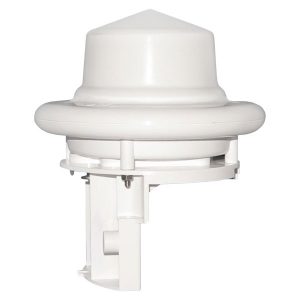
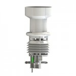
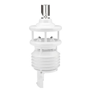
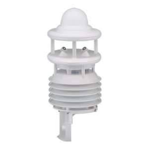
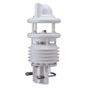
Lufft produces many models of the WS-Series line of weather stations, each with its own output of parameters. An internal script on NexSens X-Series data loggers will automatically detect the type of connected weather station and its associated parameters.
|
|
|
|
Lufft WS-Series Integration
All Lufft weather stations must have their communication protocol changed from the default UMB-Binary to Modbus-RTU for communication with X-Series data loggers. Additional settings are recommended to gather more accurate measurements from each of the stations’ parameters.
1. Setting Up a Workspace
- Configure communication directly using either a Lufft WS-Series Sensor Interface Cable or a NexSens Lufft WS-Series Sensor Configuration Cable.
- Connect the cable to the Lufft and the USB connection to a PC. Leave the sensor unpowered.
- Determine the COM port of the USB cable with the Windows Device Manager.
- Download and open the ConfigTool.NET software.
- Check the bottom right of the software to confirm the COM port is correct. If the COM port is incorrect or no COM port is available, edit an existing workspace or create a new workspace to change the COM port.
- Creating a new workspace will automatically open the “Com Channel” options.
- If editing an existing workspace, you must select the plug icon while in the “Workspace Details” to open the “Com Channel” options.

Figure 10: Workspace options.

Figure 11: COM Channel.
- Apply 12VDC power to the sensor.
- Click the ‘+’ or magnifying glass option in the top right to add or scan for a device, respectively.

Figure 12: Add, scan or import/export workspaces.
2. Connecting to a New Device
- If adding a device, insert any device name, choose the WSx-UMB device class, and insert the proper device ID. The default ID for new systems is 1.

Figure 13: Manually add a device.
- While scanning for a device, new devices will begin loading their channels once the scanning reaches class 7 device 1, since Lufft weather stations are in class 7 and have the default ID of 1.
- If connecting to a device with a changed communication protocol (i.e., SDI-12 or Modbus-RTU), visit the Backdoor Communication for Pre-configured Devices article.
- If already connected, go to the Configure Settings section to set the proper settings on the weather station.

Figure 14: Scan for a device.
3. Configure Settings
- The device settings will have populated if the software successfully read the sensor.

Figure 15: Device settings.
- To be setup properly for an X2 data logger, the following settings must be changed:
- Change communication protocol from UMB-Binary to Modbus-RTU
- Set all average intervals to 2 minutes (i.e., temperature, relative humidity, air pressure, lightning, global radiation, wind)
- Turn on Compass Correction
- Turn off the Fan (unless otherwise specified)
- Turn off the Heater (unless there is adequate 24V power)
- Set the altitude of the final deployment location (in meters).
- Set the local declination for the final deployment location in the Compass offset setting (in degrees).
- The Lufft weather station has a North arrow that must point to magnetic north during deployment. Depending on the deployment location, “true north” will have a slight offset from magnetic north due to the shifting of the north magnetic pole. Thus, an offset must be entered to correct for the difference.
- Using the NOAA Geomagnetic field calculator, enter the coordinates for the final deployment location. Click “Calculate” and a new window will appear with the declination for the deployment location.

Figure 16: NexSens headquarters declination.
- Ensure the final unit is in decimal degrees by using the FCC conversion calculator
- Remember, only the longitude has a declination. If the declination is West, the number must be negative. If the declination is East, the number must be positive.
- Ensure the final unit is in decimal degrees by using the FCC conversion calculator
- After all settings have been changed, click the ‘Write To’ up arrow in the top right to save settings.
- Optionally, save a settings template for the sensor with the ‘Export Settings’ button on the top right.
- Power down and connect the weather station to the X2 for sensor detection.

Figure 17: Write to device, and import/export device settings.
4. Automatic Sensor Detection
After adjusting the internal communication settings, the sensors and their parameters can be programmed onto the logger via automatic detection.
X-Series Script Information
The X-Series data logger includes a pre-loaded Lufft script, which is enabled by default upon shipment. For new data loggers, connecting the sensor and providing power will force the data logger to run through an automatic detection process.
For loggers with adjusted settings, use the link below to confirm the In-Situ script is enabled before running a sensor detection.
| X2 Script Number | Communication Protocol | Sensor Interface | Baud Rate | Power Type | Warmup Period (sec) | Frame |
| 1002 | Modbus-RTU | RS-485 | 19200 | Continuous | 0 | N81 |
Script Parameters
| Parameter | Unit | Associated WS-xxx models |
| Air Temperature | °C | 401, 500, 501, 600, 601, 700, 800 |
| Relative Humidity | % | 401, 500, 501, 600, 601, 700, 800 |
| Relative Barometric Pressure | hPa | 401, 500, 501, 600, 601, 700, 800 |
| Wind Speed | m/s | 500, 501, 600, 601, 700, 800 |
| Max Wind Speed | m/s | 500, 501, 600, 601, 700, 800 |
| Wind Direction | Deg | 500, 501, 600, 601, 700, 800 |
| Heading | Deg | 500, 501, 600, 601, 700, 800 |
| Solar Radiation | W/m2 | 501, 700, 800 |
| Precipitation Type | — | 600, 601, 700, 800 |
| Rain Intensity | mm/hr | 600, 601, 700, 800 |
| Total Rain | mm | 401, 600, 601, 700, 800 |
| Interval Rain | mm | 600, 601, 700, 800 |
| Lightning Events | Event/min | 800 |
| Interval Lightning Events | Event | 800 |
5. Setting up WQData LIVE
Once an X-Series data logger has finished a new sensor detection, it will automatically push the sensor configuration to the WQData LIVE Web Datacenter. Follow the three articles below to create a WQData LIVE account and a project/site. Then add the data logger to the project using the included claim code.
- Create a WQData LIVE Account
- Create a Project on WQData LIVE
- Add a Data Logger to a Project on WQData LIVE
Real-Time System Application
Real-time weather and atmospheric measurements from the Lufft WS-Series of Weather Stations are useful in various environmental monitoring applications.
Applicable Systems
Discover applicable uses for Lufft WS-Series Weather Stations.
- Dock Monitoring Systems
- Green Roof Monitoring Systems
- Inland Lake Monitoring Systems
- Large Lake Monitoring Systems
- Weather Station Systems
Case Studies
Read about specific applications using Lufft WS-Series Weather Stations.
- Cellular Data Buoys Predict E. Coli
- Using Technology to Protect Tradition
- Stone Lab Buoy Tracks Algae
- Suttle Lake Data Buoy
- Great Lakes Buoy Networks
- Educational Lake Data Buoy
- Michigan’s Muskegon Lake Sentinel
- Monitoring Toledo’s Water Crisis
- Real-Time Lake Erie Data
Weather and Atmospheric Measurements
Learn more about weather and atmospheric measurements on the NexSens Blog Page.
Sensor Manuals
For additional information on Lufft weather stations, please refer to the Lufft WS Manual.

