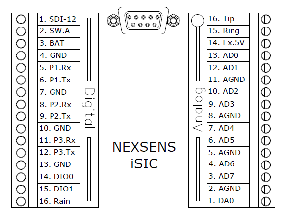
Two 16-pin un-pluggable terminal strip connectors are located inside the enclosure. Power and sensors will be connected to these terminals. The connector on the left is for connecting digital and smart sensors. The connector on the right is for connecting analog sensors. Descriptions for the pins on both connectors are given below:
A factory installed option for analog, digital, and galvanic dissolved oxygen sensor expansion is available. The interface connections for expansion are located behind the battery.

Figure 1: iSIC Digital and Analog Terminal Connections
Digital Connectors
SDI-12: Connection for SDI-12 sensors.
SW.A: 12V, 200 mA power switch.
BAT: Pass-through battery power pin (fused)
GND: Ground (digital)
P1.Rx: RS-232 Receive Pin (Port 1) – Input
P1.Tx: RS-232 Transfer Pin (Port 1) – Output
P2.Rx: RS-232 Receive Pin (Port 2) – Input
P2.Tx: RS-232 Transfer Pin (Port 2) – Output
P3.Rx: RS-485 Receive Pin (Port 3) – Input
P3.Tx: RS-485 Transfer Pin (Port 3) – Output
DIO0: General purpose Digital I/O.
DIO1: General purpose Digital I/O.
Rain: Tipping bucket rain gauge input
Analog Connectors
Tip: Telephone wire connection pin
Ring: Telephone wire connection pin
Ex.5V: 5V Excitation voltage
AD0 – AD7: Analog Inputs
AGND: Analog ground
DA0: Digital to Analog output
REV: 13H02
