iSIC and SDL500 data loggers have optional Power Management settings that can be used to conserve power for systems with a high power demand or when solar charging and battery power are limited. The Power Management settings are implemented through iChart software. Power Management allows users to turn off power-hungry devices such as cellular modems and radios, thus extending the life of the available power supply.
There are two types of Power Management settings: Power Schedules and Auto Power OFF. Power Schedules are used to turn the data logger’s communication device (cell modem, radio, etc.) on and off on set intervals or at specific times of the day. The Auto Power OFF function allows users to set a low threshold voltage, below which the communication device will power off until the battery is recharged above a high threshold voltage.
Both of these Power Management tools are intended to conserve power for data logging functions. While they cause the logger’s communication device to power off under certain conditions, the logger will continue to log data on the programmed interval unless the power falls below the minimum required for the data logger circuit board (approx. 5V) or any sensors connected (varies by device).
Setting a Power Schedule
1. Open iChart with a current project.
2. From the menu select Advanced | iSIC | iSIC.
3. Select the correct PC COM port, Connection type and iSIC Address. Press Connect.

Figure 1: Connecting to an iSIC or SDL500
4. Click the General tab and verify connection by checking the information displayed in the Status group box.
5. Click the Power Schedule tab.
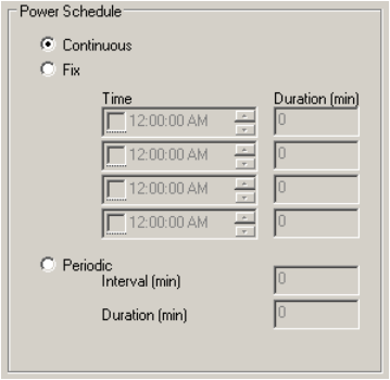
6. Choose between the Fix or Periodic options, then set the desired schedule.
WARNING: A minimum duration of 10 minutes is recommended for power schedules to allow time for connection to be established, any necessary setting to be changed, and data to be uploaded.
When the Fix option is selected, the communication device will turn on at the set times and stay on for the set Duration. For example, if the selected Time is 12:00:00 PM and the Duration is 30 min, remote communication can only be established with the logger between 12:00:00 PM and 12:30:00 PM each day.
- The maximum duration for any period is 240 minutes, so if the device is to be turned on for longer than 4 hours, break the periods up into multiple instances
- Ex. To keep the logger on from 8 AM to 5 PM set the logger as follows
Time Duration 8:00:00 AM 240 12:00:00 PM 240 4:00:00 PM 60
- Ex. To keep the logger on from 8 AM to 5 PM set the logger as follows
When the Periodic option is selected, the device will be turned on each time the specified Interval elapses and will remain on for the Duration. All Intervals reference back to 12:00:00 AM. For example, if the Interval is 90 minutes and the Duration is 10 minutes, remote communication can be established from 12:00:00 AM – 12:10:00 AM, 1:30:00 AM – 1:40:00 AM, etc.
When the Continuous option is selected, the communication device will remain constantly ON unless the Auto Power OFF function causes it to power off (see below).

Figure 2: Setting a Power Schedule
7. Click Apply to submit any changes.
NOTE: Once a Power Schedule is configured, the iChart auto-interrogation schedule must also be adjusted to allow interrogations to take place while the data logger communication device is receiving power. Click here for more information on updating the auto-interrogation schedule.
Setting Auto Power OFF Thresholds
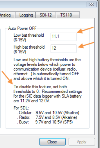
The Auto Power OFF feature is used to turn off communication devices such as radio, cellular and Ethernet modems when low battery power is available. This reserves available power for data logging functions. The low battery threshold defines the battery voltage below which the communication device is automatically turned OFF. The high battery threshold defines the voltage that must be exceeded for the communication device to be turned ON following a drop below the low battery threshold.
1. Enter the Low and High bat thresholds in the appropriate boxes. Recommended settings are listed below these boxes.

Figure 3: Auto Power OFF thresholds
2. Click Apply to submit any changes.
REV 15C31
