Replace the SD Card within an iSIC-V2
Caution!!!- Be sure to statically ground yourself prior to touching any of the electronics inside the iSIC V2 logger or the SD card itself
Tools Required:
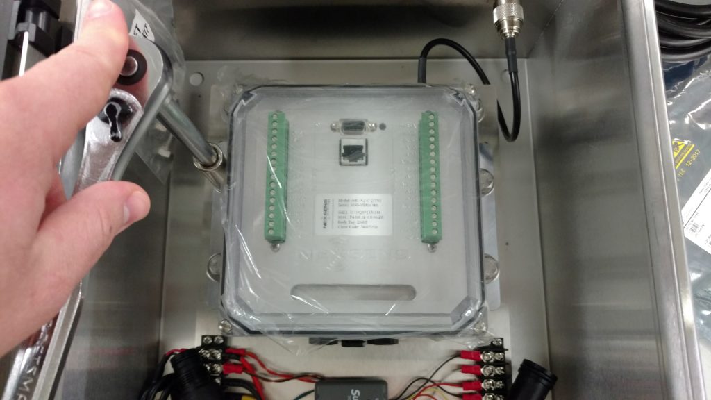
-9/16″ Socket Wrench
-5/32″ Allen Wrench
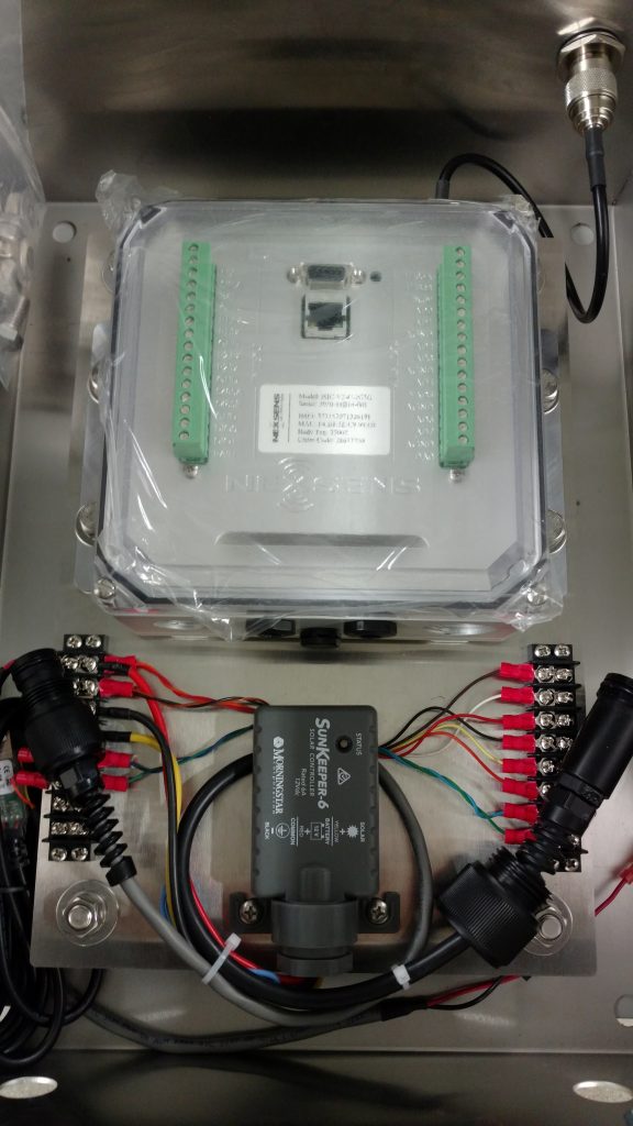
- Remove the UW-6 and UW-8 (if Equipped) connectors from the base of the iSIC V2 housing.
- Remove the (4) 3/8-16 bolts securing the V2 to the AVSS mounting plate using a 9/16 socket wrench.
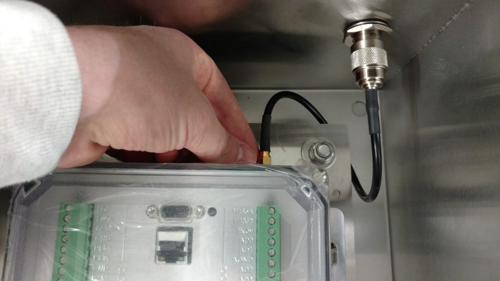
- Loosen and remove the SMA RF connector (if applicable) at the top of the V2.
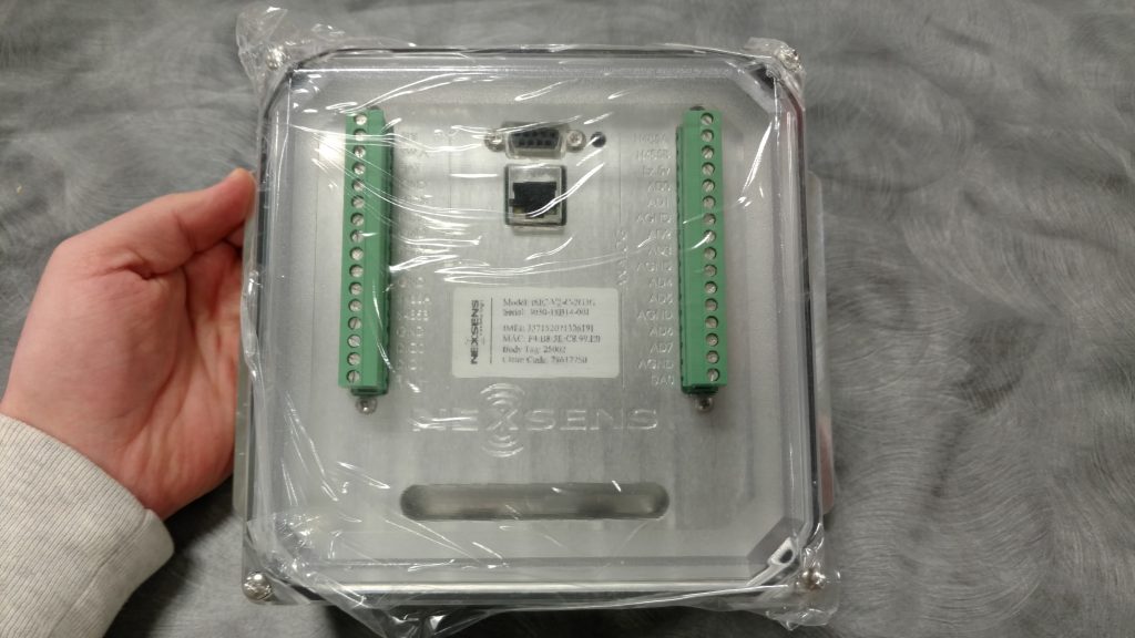
- Remove the iSIC V2 from the AVSS enclosure.
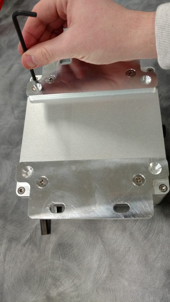
- Use a 5/32 Allen Wrench to remove the four outer screws to lift off the back plate.
- Remove the back plate to expose the iSIC V2 PCB and Cell Modem.
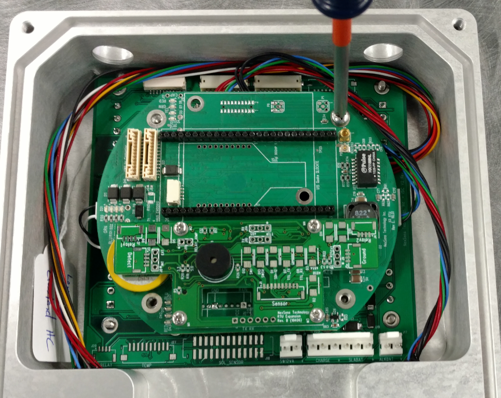
- Use a Phillips screwdriver to remove the four screws mounting the RTU PCB to the main board.
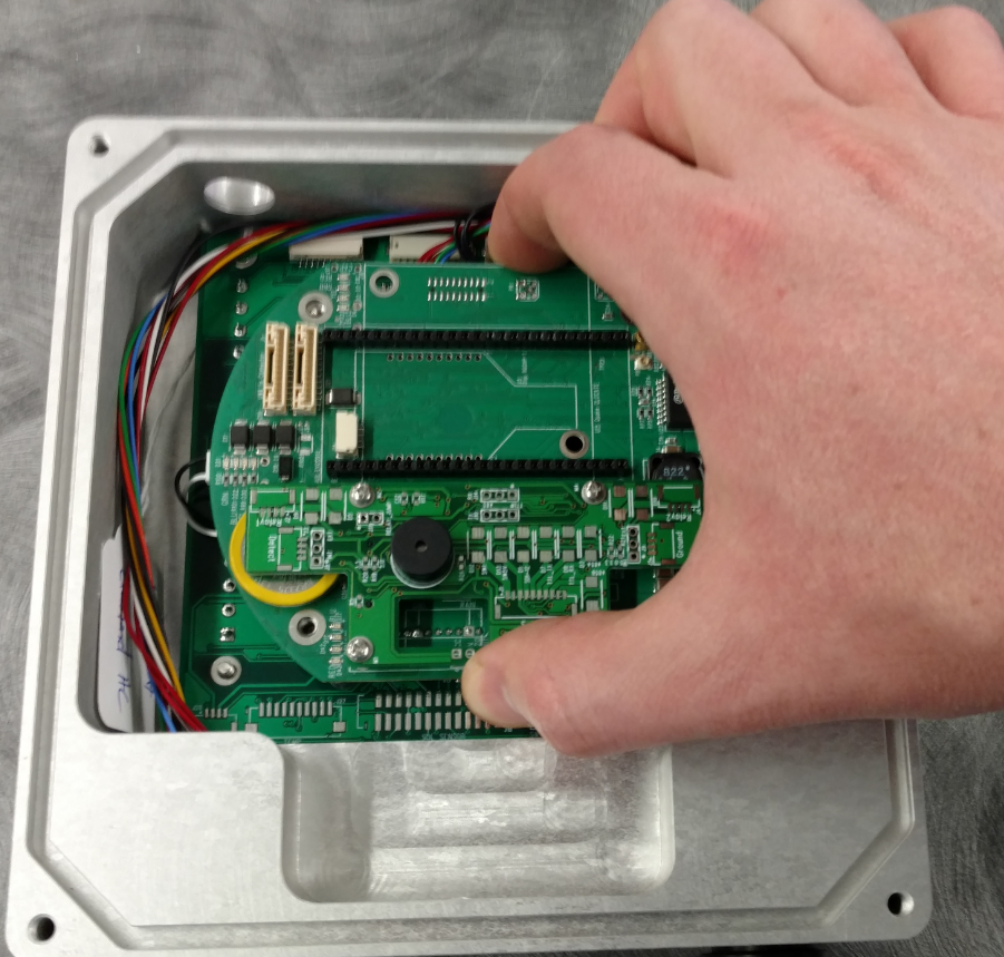
- Use even pressure on the top and bottom of the RTU board and lift upwards gently to disconnect it from the main board.
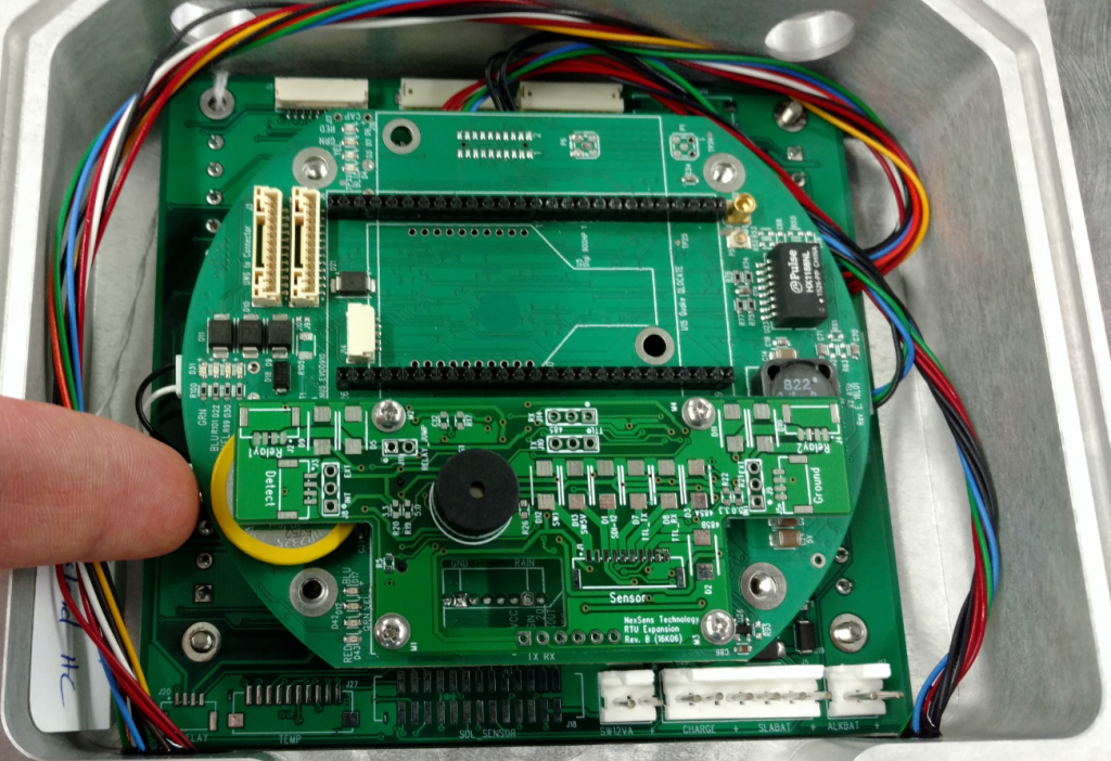
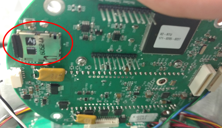
- Gently rotate the RTU board and locate the SD card slot located directly underneath the yellow RTC battery .
- Push the SD card inwards slightly until a click is heard and pull it out to remove.
- Install the new SD card identically to the original and click into place.
- Carefully align the RTU board connector pins back to the main board socket and use even downward pressure to put it back in place.
- Secure the RTU board in place using the (4) Phillips screws and lock washers removed prior.
- Re-assemble the iSIC-V2 system in reverse order as covered in steps 1-6


