
Enable Cellular Communication on an X-Series Data Logger
To enable cellular communication on an X-Series data logger, the user must configure the Packet Data Protocol (PDP) context settings in CONNECT software. The PDP context includes three key parameters:
- Local Context Identification (cid)
- PDP Type
- Access Point Name (APN)
These settings define the local cellular carrier (e.g., Verizon, AT&T, T-Mobile) used by the modem and SIM card, and ensure data packets are properly routed to the WQData LIVE Web Datacenter. The steps below outline how to set the PDP context for cellular communication.
Note: All X3 data loggers are shipped with an active SIM card.
- If cellular service is purchased through NexSens, the included SIM card will remain active for the duration of the plan, and no additional setup is required.
- If service is not purchased through NexSens, the SIM card will remain active for a three-month trial period. This allows for initial testing without additional configuration.
- Only follow the steps below if you are installing and using a user-supplied SIM card.
1) Power On the Modem
- Establish Direct Communication with the Data Logger
- Use the supplied USB cable to connect the X-Series data logger to the PC.
- Launch the CONNECT software.
- Depending on the CONNECT version, the cellular configuration can be found at the following:
- Version 4: Tool → X2 RTU → Cellular
- Version 5: Tool → Communication → Cellular
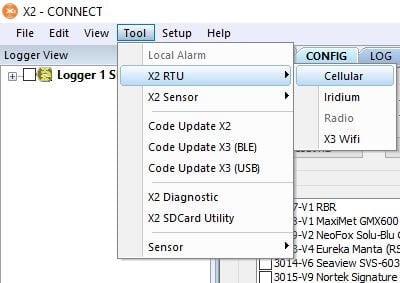
Figure 1: Cellular configuration in V4. |
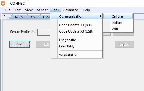
Figure 2: Cellular configuration in V5. |
- Power On the RTU Board
- Click Turn Power ON to start up the logger’s RTU board.
- The RTU controls communication with the internal modem and SIM card.
- NOTE: During the first few seconds after sending the command, CONNECT may output Fail to switch RTU power – Ecode = -7 – ‘Modbus receive timeout.’
- This typically occurs when the X3 runs internal processes, such as right after powering on or during a scheduled logging/transmission interval. After a few seconds, CONNECT should display Successfully sent RTU power CMD. If the error continues or shows Fail to Power ON, cycle the power and try again.
- Once successful, a timer will appear on the screen.
- Allow up to 30 seconds for the startup process to complete.
- A confirmation message will appear once RTU Power is successfully enabled.
- Click Turn Power ON to start up the logger’s RTU board.
Note: The RTU automatically powers down once it reaches the scheduled transmit interval. If this occurs during setup, turn the RTU on again to continue direct communication. To prevent this while adjusting settings, temporarily set the transmit interval to 0 before turning the RTU back on.
2) Verify and Configure the Current PDP Context Settings
- Review the Current PDP Context Settings
- From the Direct Command list, select AT+CGDCONT? and click Send.
- The logger will return the current PDP context configuration. The key settings are in bold in the response below:
- +CGDCONT: 1, “IPV4V6″,”teal”,””,0,0,0,0<CR><LF>
- +CGDCONT: <cid>, <PDP Type>,<APN>,””,0,0,0,0<CR><LF>
- If the cid, PDP type, or APN are incorrect, proceed to the next step to update them.
- If the current settings are correct, move to section 3 to test the cellular connection.
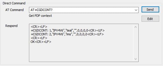
Figure 3: Example response to AT+CGDONT? command.
- Enter the correct PDP Context Information
| Parameter | Description | Typical Value(s) |
| cid | Carrier-specific context ID for general internet connection | 1 = AT&T, T-Mobile, or most International carriers 3 = VerizonNOTE: For X3 data loggers, always use cid 1. |
| PDP Type | IP address format assigned to the PDP | IPV4V6 (works with most carriers; confirm with cellular provider if issues occur) |
| APN | Access Point Name for carrier network | Select from drop-down or enter manually in proposals (e.g., “vzwinternet”) |
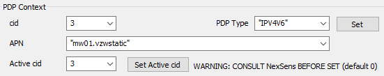
Figure 4: Example of setting a custom APN on a 4G Verizon data logger.
- After entering the cid, PDP Type, and APN, click Set.
- A prompt will appear indicating whether the command was successful.
- If multiple PDP contexts are configured with different cids, ensure that the Active cid is set to match the carrier currently in use.
- To verify the settings, read back the APN configuration using the AT+CGDONT? direct command.
- Confirm that the correct cid, PDP Type, and APN are properly listed on the modem.
3) Test Network Connection
After configuring the PDP Context settings, test the modem’s network connection.
Verify Adequate Signal Strength and Stability
- Read the Signal Quality of the system
- Read the signal quality multiple times to ensure it is stable.
- If unstable, confirm the PDP Context settings are set up correctly. Signal strength can be improved by forcing the modem to lock onto a specific carrier:
| If You See… | Do This… |
| Signal between –51 dBm and –75 dBm | Acceptable – proceed with configuration |
| Signal weaker than –75 dBm | Follow the article linked below for troubleshooting steps* |
| BER above 5% | Follow the article linked below for troubleshooting steps* |
*X-Series Logger Telemetry Signal Strength Values
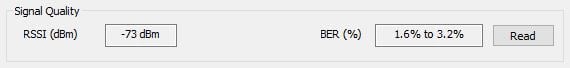
Figure 5: Example of adequate signal strength.
Test Connectivity with Custom 1 Command
Review the Custom 1 command, edit (if necessary), and then click Send. The Custom 1 command has three built-in commands:
| Command | Purpose | Key Details/Parameters |
| AT+CMEE=2 | Enables extended error reporting | Returns descriptive error messages instead of numeric codes for easier troubleshooting
If successful, the response should be: |
| AT#SGACT=x,x | Activates or deactivates the PDP context | First x = Active cid Second x = Action (0 = Deactivate, 1 = Activate) Examples:
Select Edit in CONNECT to adjust this command to match the correct cid (i.e., AT&T/International OR Verizon). |
| AT#HTTPCFG=1,”wqdatalive.com”,80,0,””,””,0,35 | Configures modem HTTP profile for WQData LIVE communication | If successful, the response should be: <CR><LF>OK<CR><LF> |
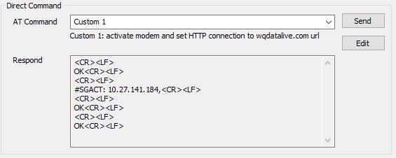
Figure 6: Successful Custom 1 command response.
| If You See… | Do This… |
| IP address returned after AT#SGACT (See figure 5) | Connection successful – proceed to Custom 2 command |
| “SIM not inserted” | Power down the system, check SIM seating and reinsert |
| “Activation Failed” | Review PDP Context settings. If correct, contact carrier to ensure plan is active and set for a M2M plan. |
| “Requested Service Option not subscribed” | Contact carrier to ensure plan is active and set for a M2M plan. |
| “Unspecified GPRS error” | Check carrier compatibility with modem/antenna bands |
Test Connectivity with Custom 2 Command
If a succcessul Custom 1 command response is returned, continue to the Custom 2 command and select Send. The Custom 2 command has three built-in commands:
| Command | Purpose | Key Details/Parameters |
| AT#HTTPSND=1,0,”/data/lastupload”,57,0 | Sends an HTTP POST request to the WQData LIVE server | If successful, the response should be: <CR><LF>>><CR><LF>OK<CR><LF> |
| DevUID=000dffffffffffff4e4549618001000f_00100010&ParmNo=1 | POST body content sent in the HTTP request | If successful, the response should be: <CR><LF> #HTTPRING: 1,200,”application/json”,32<CR><LF> <CR><LF> |
| AT#HTTPRCV=1 | Retrieves the HTTP response from the WQData LIVE server | If successful, the response should be: <CR><LF> <<<{“TStamp”:”2022-04-28 17:00:00″}<CR><LF> OK<CR><LF> |
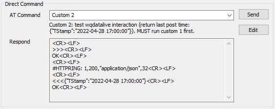
Figure 7: Successful Custom 2 command response.
- If the connection attempt fails, the modem may return:
- NO CARRIER – The SIM card is unable to latch onto a local cellular carrier. This likely indicates an issue with the cellular account. However, SIM cards can be forcibly latched onto a carrier following the article below:
- Force a Modem to Lock onto a Specific Carrier
- After following this process, try the Custom 1 and Custom 2 commands again.
- Force a Modem to Lock onto a Specific Carrier
- NO CARRIER – The SIM card is unable to latch onto a local cellular carrier. This likely indicates an issue with the cellular account. However, SIM cards can be forcibly latched onto a carrier following the article below:
Set up WQData LIVE
After successfully configuring the network connection and confirming valid responses from both the Custom 1 and Custom 2 commands, navigate to the WQDATA tab in CONNECT. Use the available options (in the link below) to transfer data from the logger to WQData LIVE.