
Mooring NexSens Data Buoy Platforms
The purpose of this article is to provide resources and guidance for designing a mooring system to securely deploy NexSens data buoys. It contains only general information on the important considerations and available mooring options.
Every deployment is unique and depends on factors such as local weather conditions, currents, wave heights, water depth, tidal or other water level fluctuations, and potential debris, biofouling, or ice loads. Developing an effective mooring strategy requires an understanding of these application-specific criteria.
Proper mooring design is often developed through years of experience with various deployment scenarios. For first-time mooring designers, it is best to include an experienced marine engineer and source materials locally.
NexSens Technology supplies mooring hardware to support user-designed systems but does not endorse any particular mooring strategy for any specific application and does not take responsibility for mooring performance or damage resulting from mooring failure.
Design Considerations
Buoyancy
Buoyancy is the upward force exerted on the buoy hull when it is deployed in the water. The force is equivalent to the weight of the displaced water.
Gross buoyancy refers to the total buoyant force a buoy would experience if it were completely submerged. It is based on the full volume of the buoy and the average density of water.
Net buoyancy is the buoyancy remaining after accounting for the weight of the buoy, including ballast and payload (sensors, batteries, mooring hardware, etc.). It is calculated as such:
Net Buoyancy = Gross Buoyancy − Weight of Buoy (including ballast and payload)
The net buoyancy must always remain positive for the buoy to float. However, the ballast and payload should never exceed roughly 50% of the net buoyancy to ensure that the buoy does not sink even in the case of extreme conditions, moisture intrusion, biofouling loads, or minor damage to the hull. If the desired payload causes an exceedance of this threshold, the payload should either be reduced or additional buoyancy, such as subsurface flotation, should be added to compensate.
Buoy Ballast and Stability
Ballast refers to the weight added to a buoy to help it maintain proper orientation and stability in the water. Ballast ensures that the buoy floats upright or in a specific position.
Stabilizing a buoy is best handled by adding weight to the rigid frame mounted below a buoy rather than relying on the mooring weight or other flexible components to act as ballast. A non-flexible ballast provides better support and encourages the buoy to move in an up-and-down bobbing motion with the wave action rather than rocking back and forth. Rocking motion is not desired as it increases the risk for periodic submersion and excessive splashing on the top of the buoy hull and solar tower components, while also causing stress on the structure, fasteners, and instrument mounts.
Some buoys may be stable without any ballast weight added, while others have minimum recommendations that also vary based on environmental conditions. Additionally, the weight associated with biofouling growth can impact the buoy buoyancy and mooring performance and should be taken into consideration during mooring design and maintenance planning.
Ballast weight recommendations are available in the selected buoy’s user guide.
Buoy Freeboard
Buoy freeboard is defined as the vertical distance between the waterline and the top of the buoy hull above the water.
Freeboard should be sufficient to prevent frequent swamping or splashing over the top of the buoy hull, though not excessive such that it contributes to buoy instability (see buoy ballast). A general rule of thumb is that at least two thirds of the buoy hull and not less than half should be above the water surface.
If excess mooring weight results in insufficient freeboard, auxiliary floatation (either surface, subsurface, or a combination of both) should be added to increase the freeboard.
Anchors
Pyramid anchors are most common for buoy applications and are designed to provide a holding power roughly 10x their dry weight once they penetrate and are fully embedded in the bottom.
Other buoy anchoring options can be accomplished with steel shapes (railroad wheels or rail) or concrete slabs. Common boat anchors, such as kedge, plow, Danforth or mushroom anchors can be used on small buoy applications.
Lifting Points
All NexSens buoy models have topside lifting eyes located near the base of the solar tower. These are sufficiently strong that a buoy can be lifted from a single top-facing lifting eye via crane or winch for removal or deployment when required. Care should always be taken to avoid damaging any solar panels, topside sensor mounts and sensors connected to the instrument cage when lifting and moving a buoy.
Buoy lifting should always take place from the specified lifting eyes and never from the solar tower. A support rope may be attached to one or more lifting eyes during deployment to make it easier to connect to the eyes from larger vessels, provided that the rope is rated for the weight it will support and is regularly inspected for damage or degradation, particularly before taking into use.
Important Note: Lifting eyes are rated for carrying the weight of the buoy only and should not be used to lift mooring hardware components, especially heavy anchor loads, which should always be lifted by their own support lines.
Data Buoy Mooring Types
There are three commonly used mooring types for data buoy applications:
- Catenary moorings
- Semi-taut two-point moorings
- Inverse-catenary (S-shape) moorings
Catenary Moorings
For shallow deployments with minimal wind, wave and current loading, most data buoys utilize catenary moorings. Shallow deployments can be designed with all chain or a combination of heavy bottom chain and light water column chain. Deeper water moorings may need to use a combination of chain and rope.

Figure 1: Example catenary mooring deployment with single chain for shallow waters. |
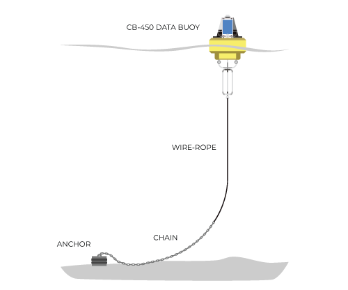
Figure 2: Example catenary mooring with combination of rope and chain for deeper waters. |
Small-Buoy Catenary Moorings
Additional surface or subsurface floatation may be required for smaller buoyancy buoy applications where the floatation may not be adequate to support the mooring weight. Extra floatation can also free motion for wave measurement applications or offer additional resistance to horizontal loading.
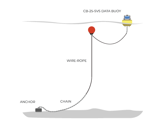
Figure 3: Example small-buoy catenary mooring with subsurface flotation. |
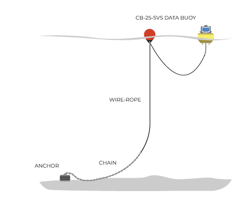
Figure 4: Example small-buoy catenary mooring with surface flotation. |
Horizontal Loading
As wind, wave and current loads increase, the buoy is driven away from the anchor and mooring can be pulled taut resulting in the buoy listing to one side. Damage can result with topside equipment and solar panels becoming submerged. Additional surface or subsurface floatation may be required.
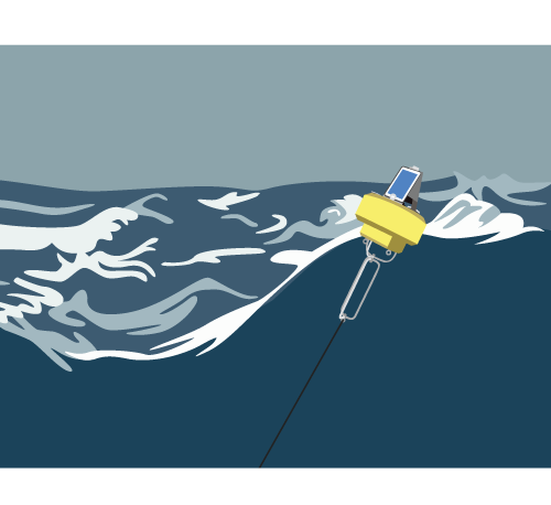
Figure 5: Depiction of horizontal loading resulting in buoy listing to one side. |
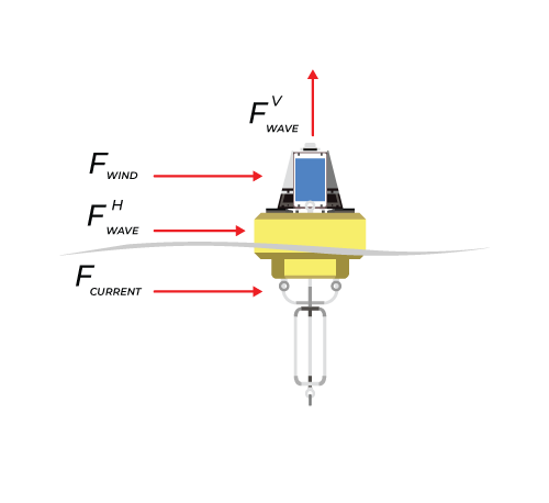
Figure 6: Force diagram representing external forces acting on buoys in natural environments. |
Semi-Taut Two-Point Moorings
For calm, shallow water with limited horizontal loading, semi-taut two-point moorings can be utilized. These moorings are useful for suspending sensor lines by pulling the mooring lines free and clear. Rough water, shifting bottom or horizontal loads can tangle two-point moorings and lead to chafing and cable failure. Use this mooring type only in controlled and calm applications.
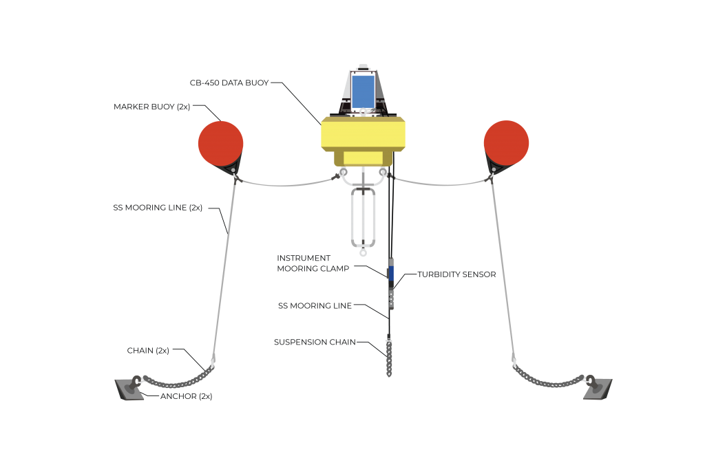
Figure 7: CB-450 data buoy with semi-taut two-point mooring setup.
Inverse-catenary (S-shape) moorings
Inverse-catenary moorings are often referred to as S-shaped moorings. Floats and weights on the mooring lines create an S-shape, which provides spring action in the water column. Waves and water level changes are easily managed. This mooring type is most common on deep water deployments but has utility in shallow, rough water applications.
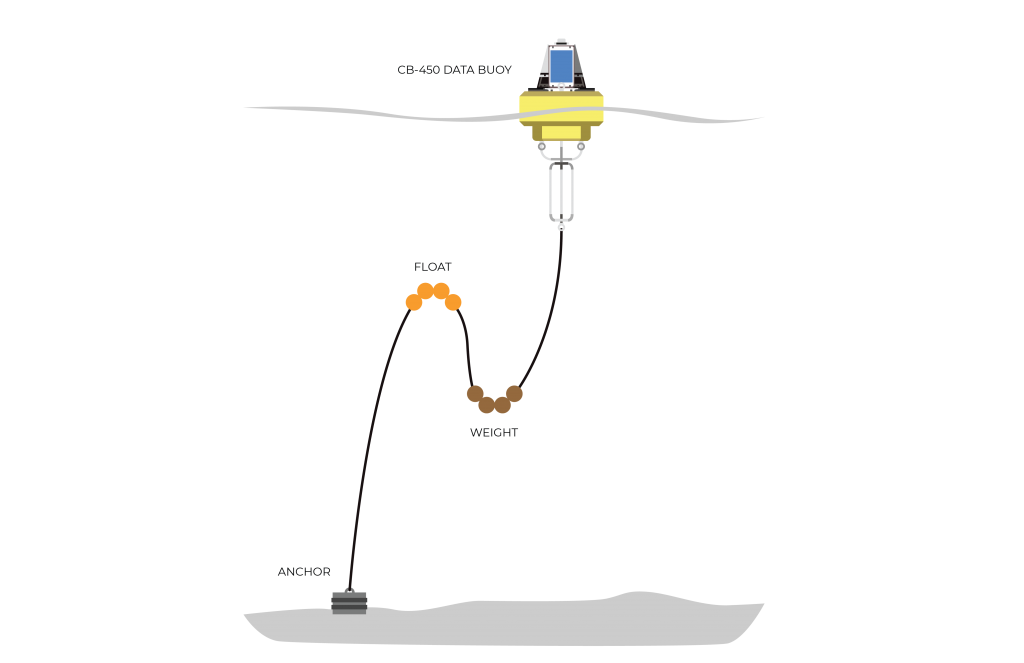
Figure 8: Inverse catenary (S-shaped) mooring diagram.